Photo Gallery
This page contains additional images of the project, particularly those taken during prototype construction. Images are presented in reverse chronological order, with the most recent progress images appearing at the top.
Build and Test Day: Power Systems (4/3/21)
The ninth build day focused on ensuring the function of the solar panels, by connecting and testing the systems involved.
Click to Expand Gallery
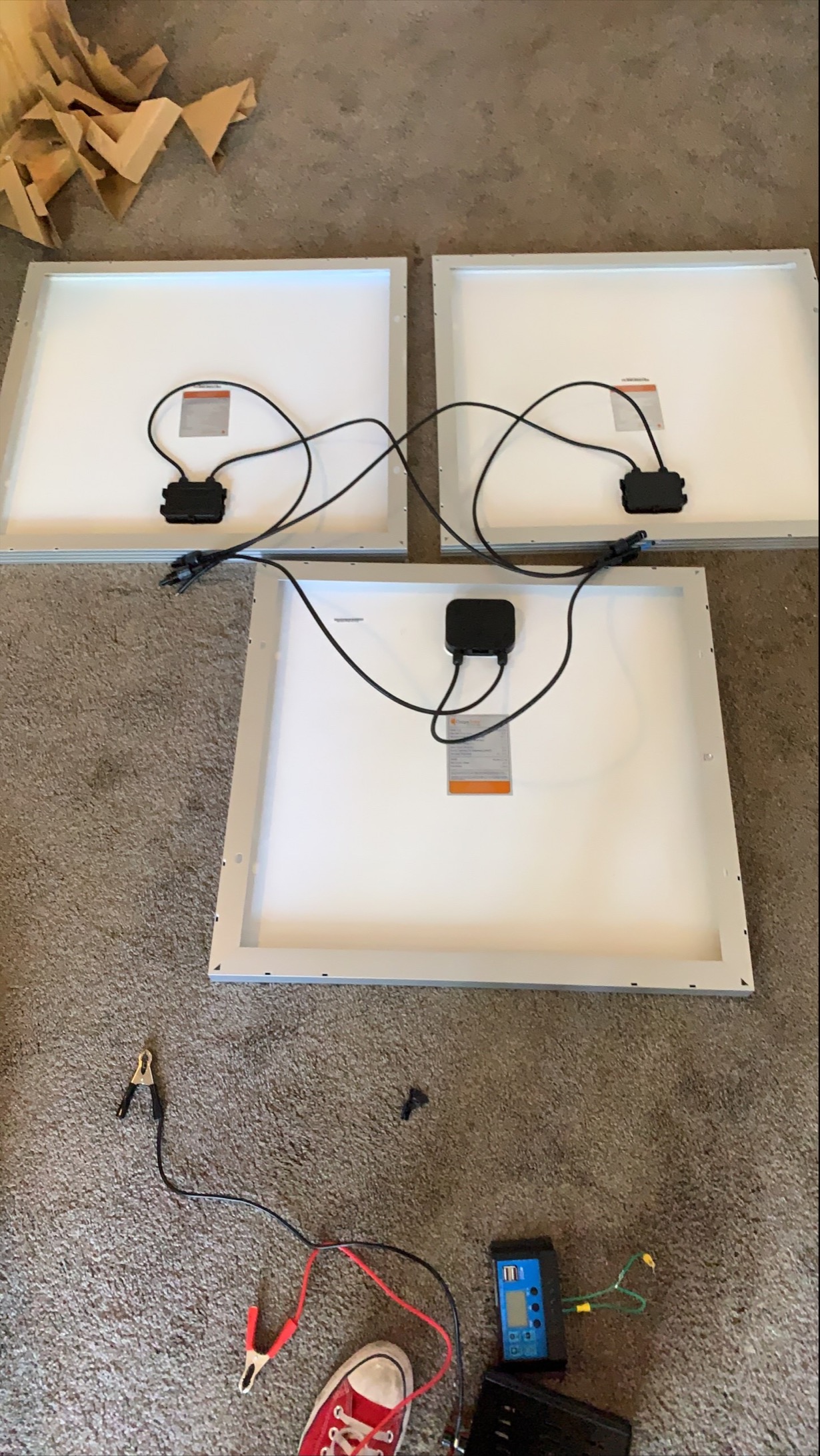
Connecting the Panels
In order to generate the required amount of power, the team connected 3 identical solar panels in parallel, with the intention of maximizing the output voltage.
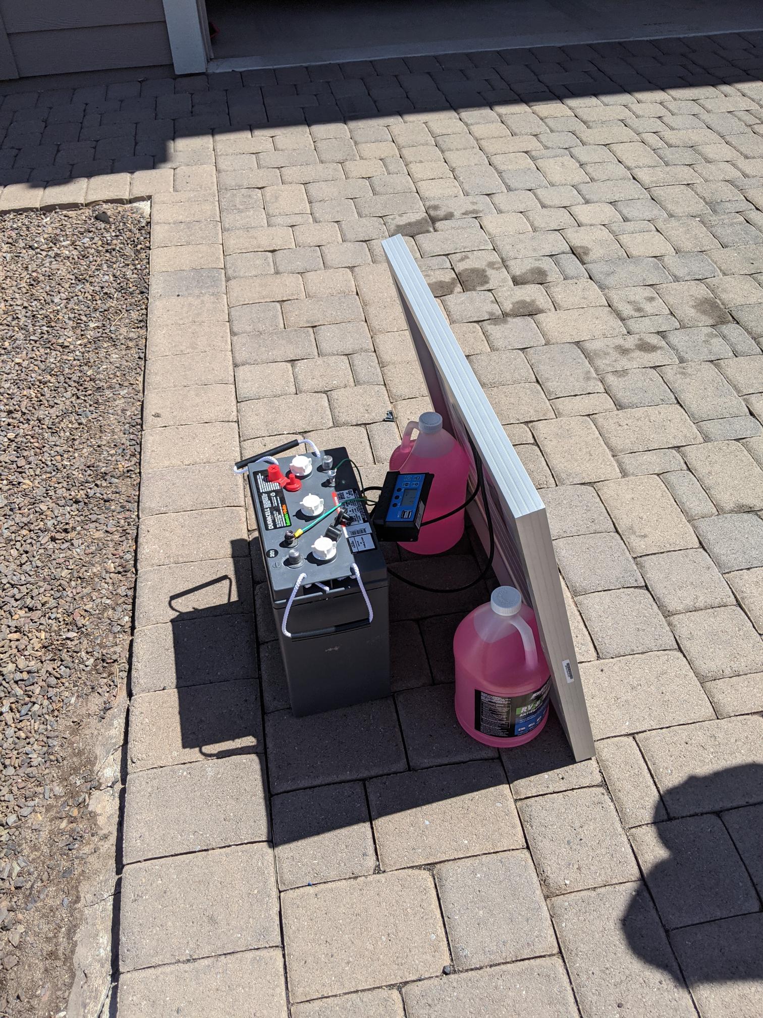
Panel Testing
Once they had connected the panels in parallel, the team tested each of them with the battery and controller system, to ensure proper integration and functionality of the system. This failed to charge the battery, suggesting that the panels provided insufficient voltage for the battery; the battery also failed to communicate properly with the inverter, suggesting incompatibility between the two devices.
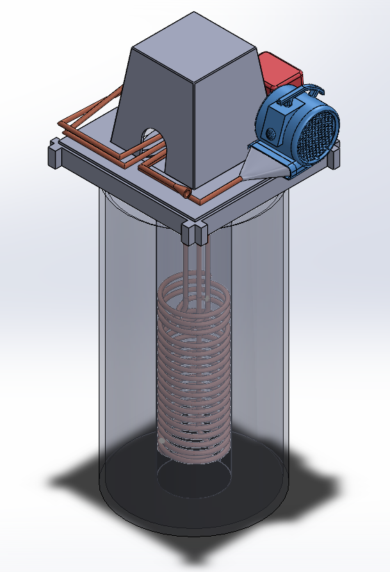
Finishing CAD Touches
While the build team worked to ensure functional power supply, the remote students added the final key touches to the CAD model, and began work on a drawing. Shown here is the added blower and blower piping.
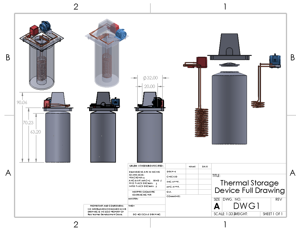
CAD Drawing
This drawing shows front and side views of the device, isometric views, and the removed charge and discharge loops. It also includes certain key dimensions.
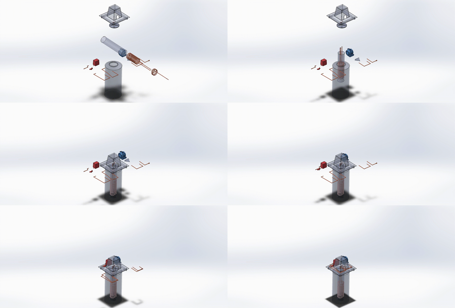
CAD Exploded View
Shown here is the most current version of the exploded views used by the team.
Test Days (3/22/21, 3/27/21, and 3/31/21)
The team attempted to implement full, 8-hour tests of the charge and discharge loops a total of three times across three separate test days. These test attempts are described here.
Click to Expand Gallery
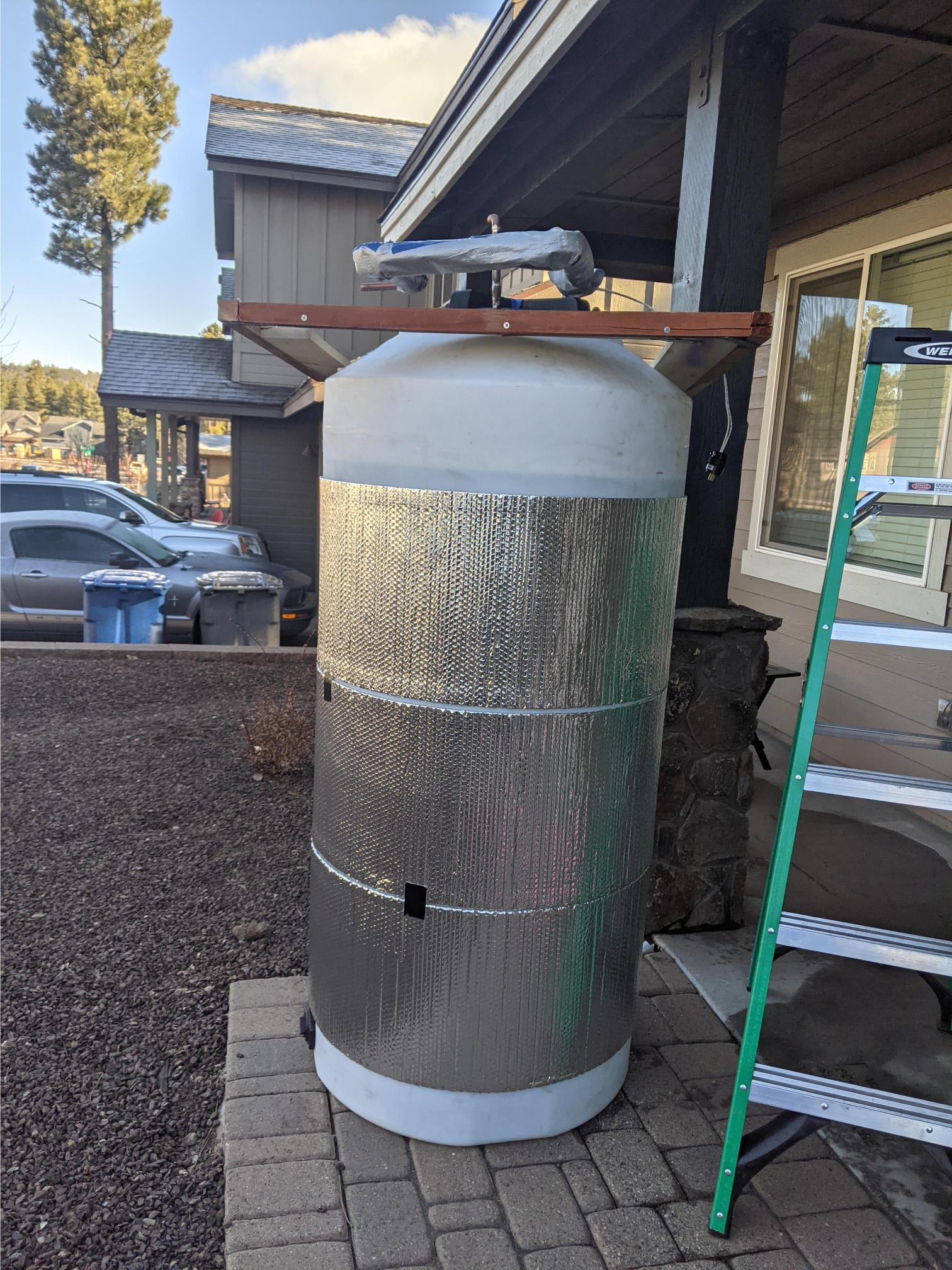
First Test Attempt (3/22/21)
After starting this test, the team found that the reservoir had a significant leak resulting from sealant failure, as well as a minor leak in the tank drain cap that would become a more significant problem over the course of the 8 hour test. The latter was fixed with teflon tape, which can be seen on the bottom left of the tank in the above image, while the reservoir was sealed properly with an o-ring. Then, piping was threaded into the reservoir, and silicone sealant was to prevent leaks around the piping.
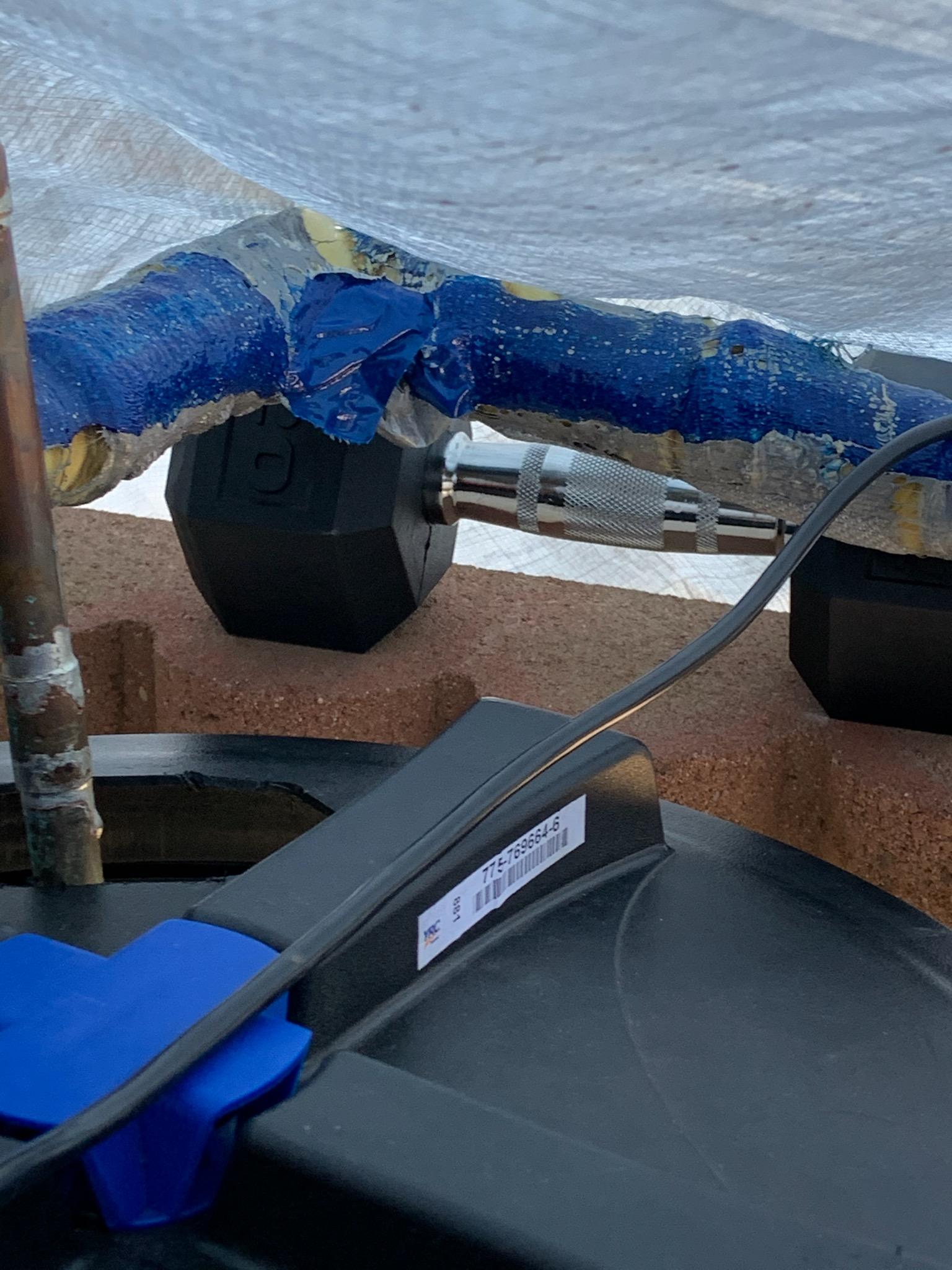
Second Test Attempt (3/27/21)
After running the heating tape and circulation loop for some time, the team found that parts of the insulation, a tarp covering the device, and the duct tape on and around the heating tape had melted onto the device. The tarp had been used in place of the cap due to fit issues, and likely melted along with the other components as a result of prolonged exposure to the heating tape. In preparation for the third test, the tarp, insulation, and duct tape were cut away, and the heating tape was re-wrapped with electrical tape.
Third Test Attempt (3/31/21)
Once the issues with insulation, the tarp, and melting plastic had been addressed,the team was able to implement a full 8 hour system heating test, shown in the video above. They found that water temperature increased over the course of the test, as did the temperature of the heating loop and tape. After 8 hours, running the discharge loop showed that the air temperature reached equilibrium with the tank temperature, and thus demonstrated a notable temperature difference across the inlet and outlet.
Build Day Eight: Pipe Sealing and Insulation (3/20/21)
The eighth formal build day was focused on sealing remaining leaks and insulating the copper piping, so as to prepare the prototype system for more strenuous, lengthy tests.
Click to Expand Gallery
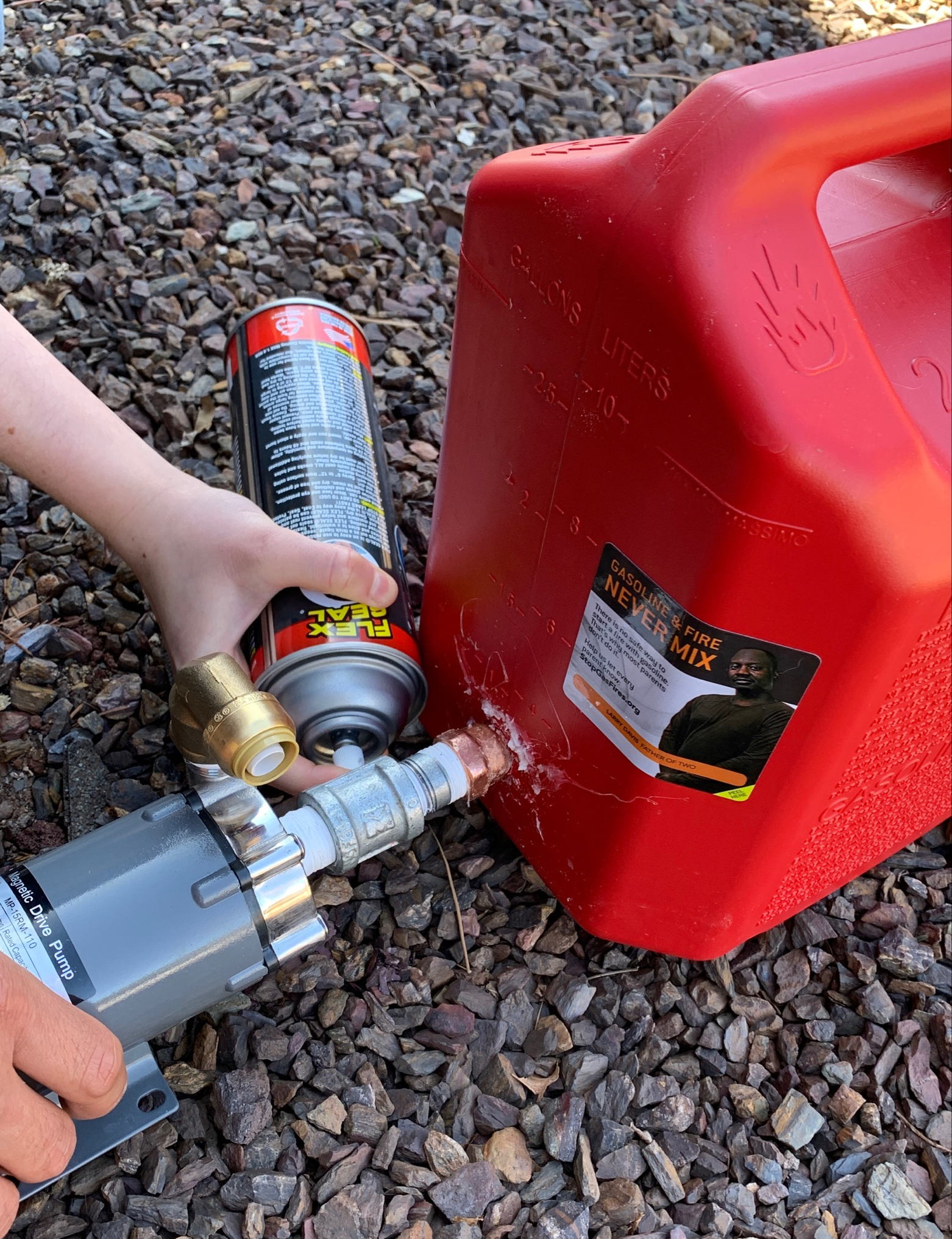
Sealing the Reservoir
In order to further combat the reservoir leaking working fluid, the team applied a layer of spray-on sealant. Ideally, this should further reduce losses and ensure that the heating loop can run for as long as possible.
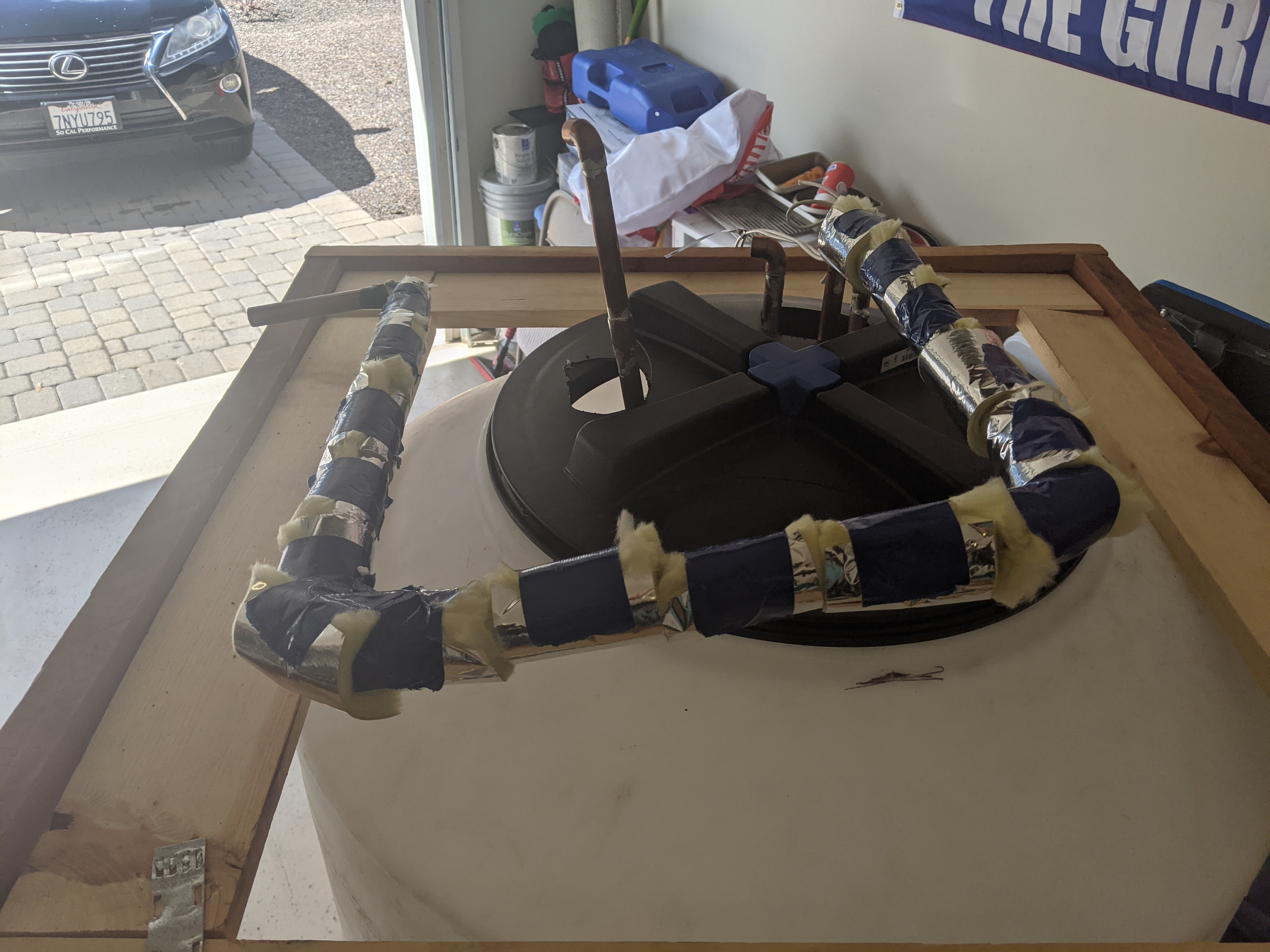
Pipe and Heating Tape Insulation
In order to minimize both thermal losses and the risk of accidental burn, the team insulated the exterior pipes heavily. This was done with an inner layer of fiberglass around the heating tape and an outer layer of mylar to maintain shape and prevent spread of fiberglass particles.
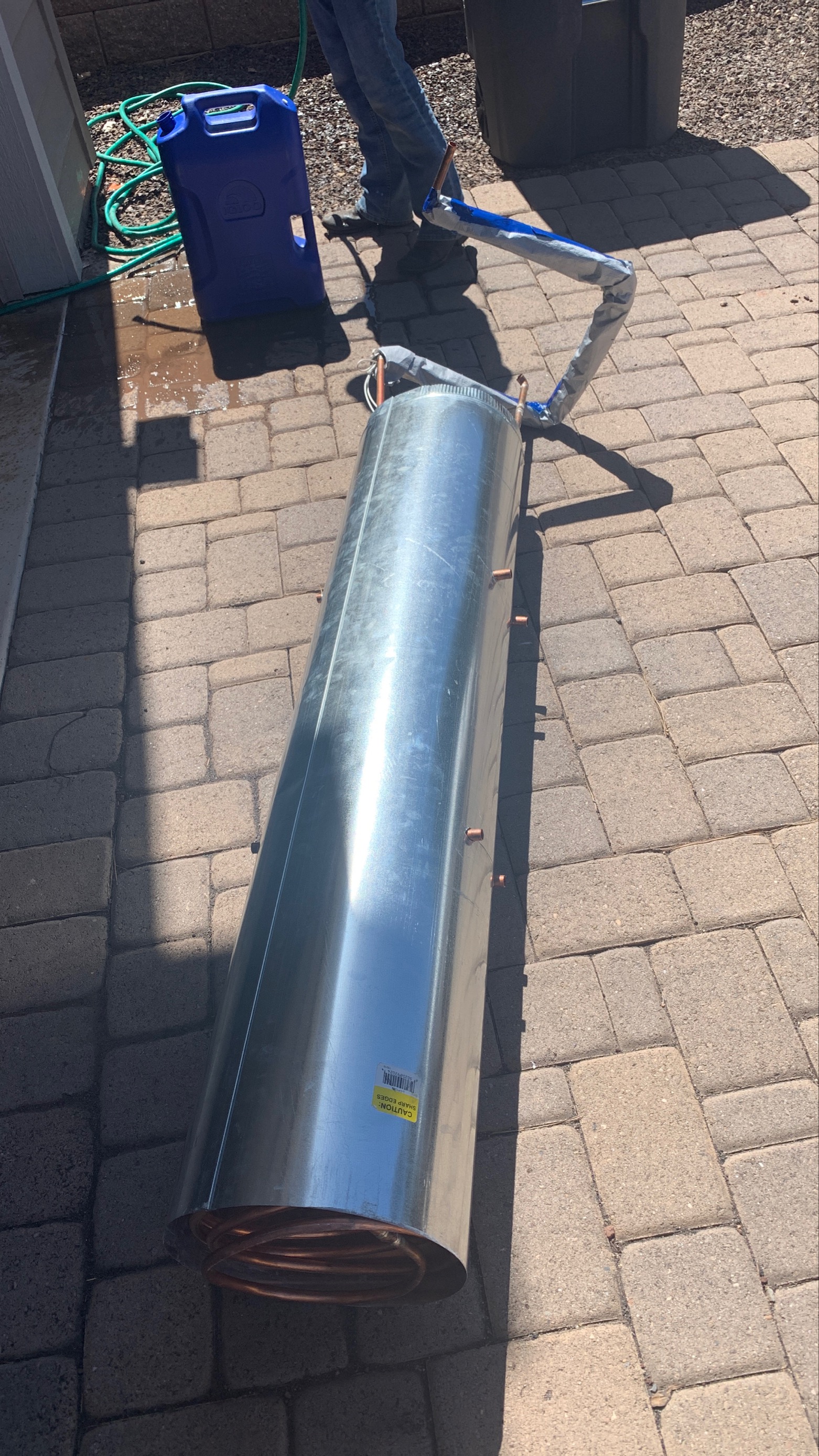
Removable HX Package
In between major tests, the team removed the nested heat exchangers within their duct housing, both to check for leaks and to facilitate device storage.
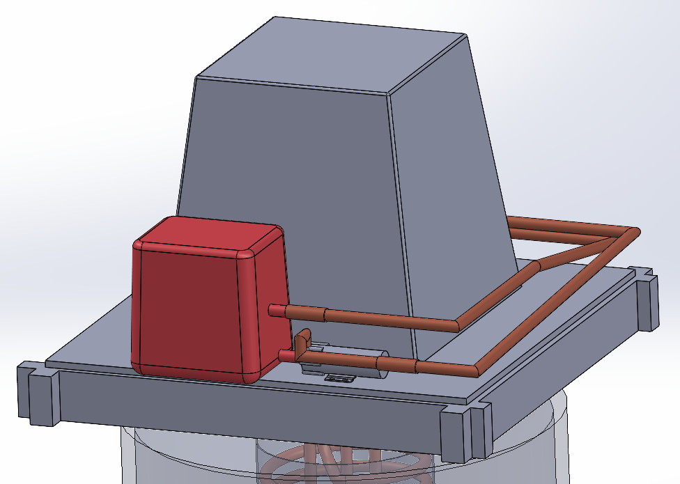
CAD Fixes and Detailing
While the rest of the team was fixing leak and insulation issues, the remote student worked to improve certain broken features in the CAD, in addition adding pipes and piping to connect the heat exchangers to the pump and reservoir.
Build Day Seven: Continued Flow Testing (3/13/21)
The seventh formal build day focused on ensuring reliable operation of the pump and blower circulation systems in advance of Hardware Review 2.
Click to Expand Gallery
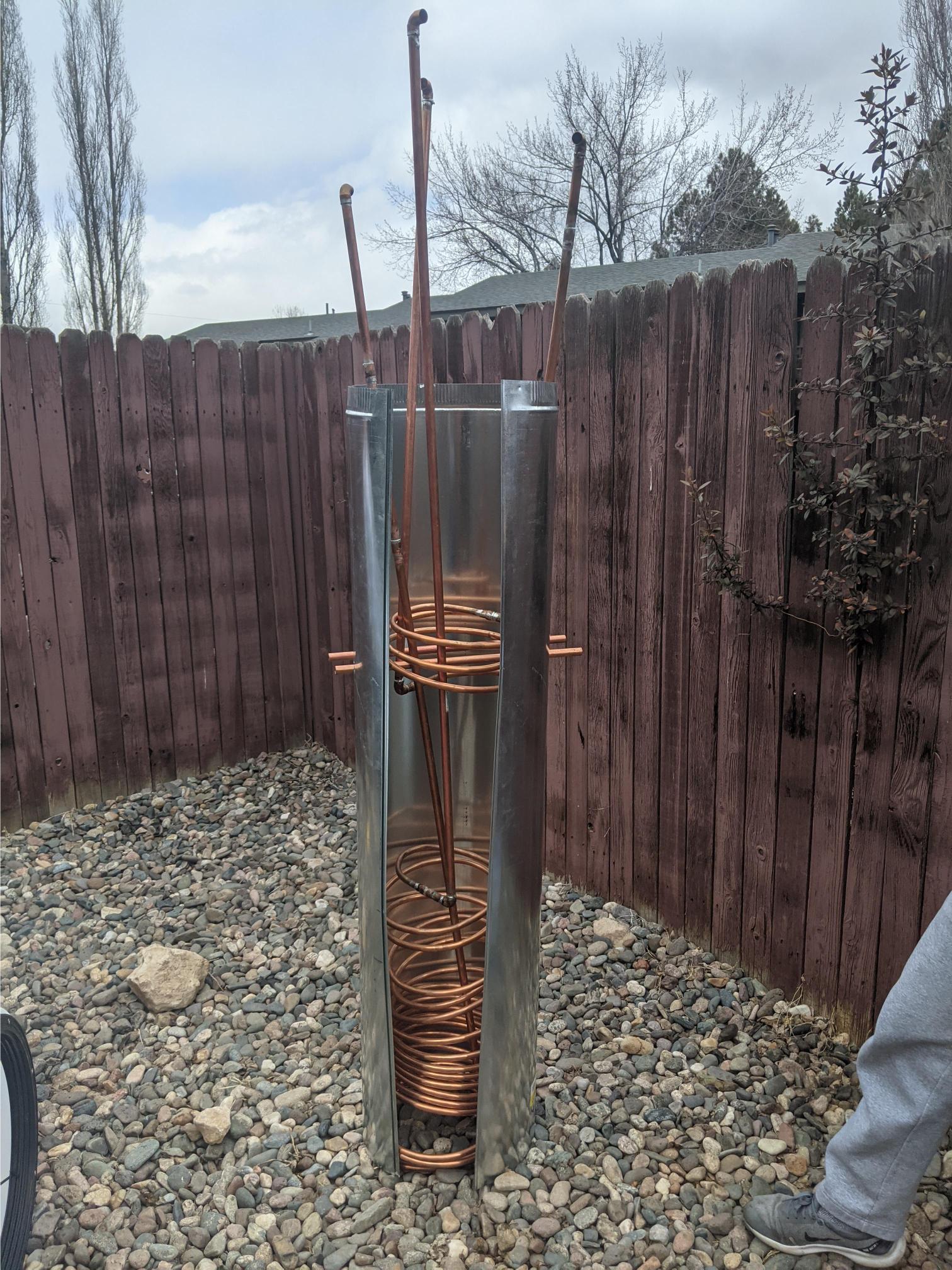
Current Heat Exchanger Stack
After early airflow tests demonstrated that the losses associated with the original liquid-to-air heat exchanger were too great for the blower to overcome, it was necessary for the team to reduce the heat exchanger's length. This shortened exchanger is shown in the image above as part of the full heat exchanger stack. Compare to Build Day Four for demonstration of this change.
Loaded Platform
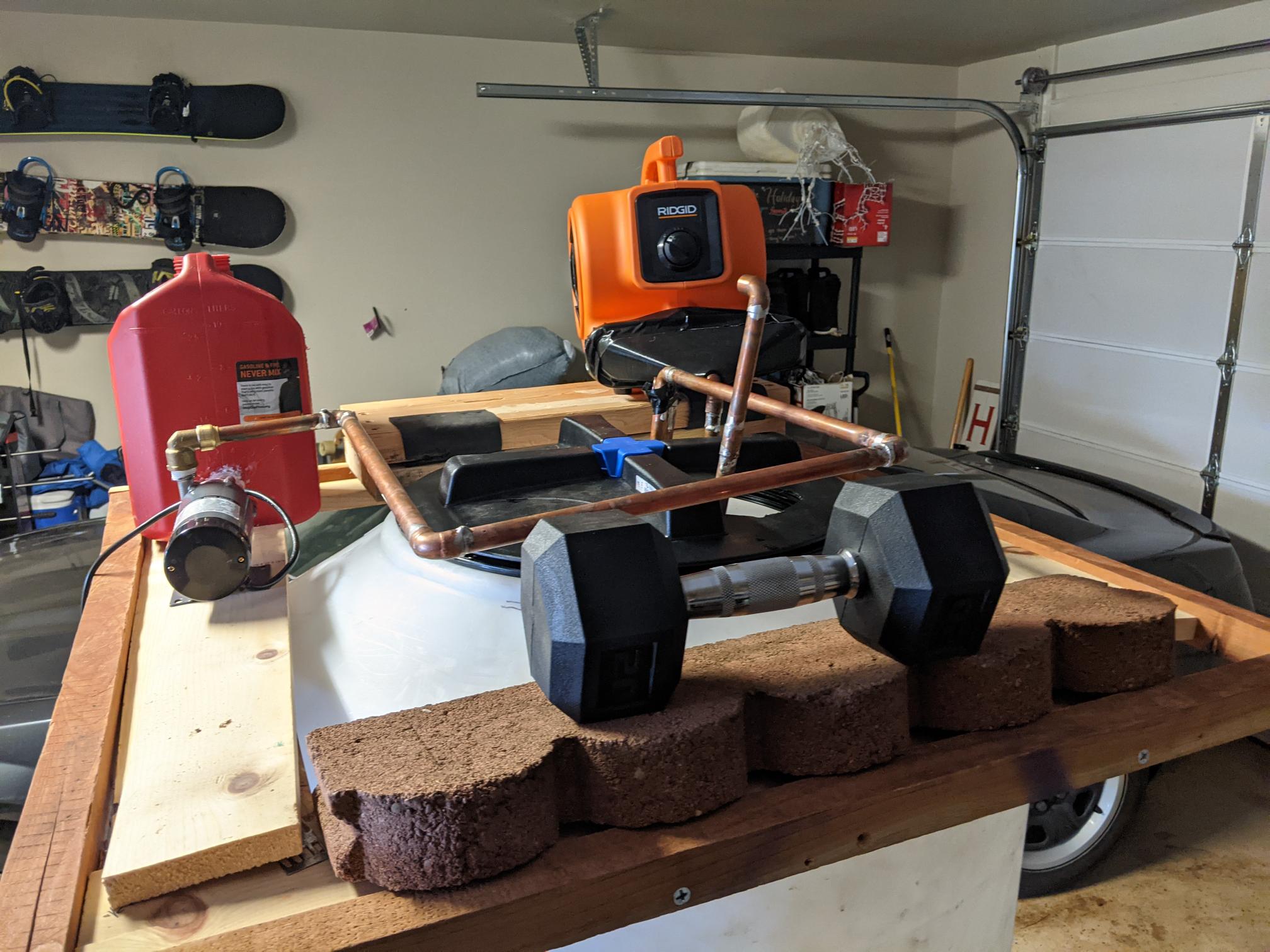
After the heat exchanger stack was checked and reinserted, the team ensured that the tank platform was correctly loaded with the pump, blower, reservoir, and counterweights. If the loading is evenly distributed this should ensure cap stability, reducing the risk of dropping components or overturning the tank.
Installed Heating Tape
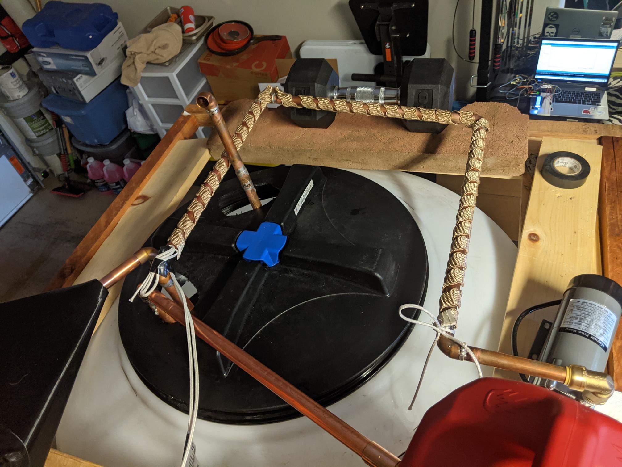
After performing the basic air and liquid flow tests, the team moved on to test the efficacy of the heating tape. Shown above is a top-down image of the tape organization, showing how it encompasses the section of pipe immediately after the pump outlet, to maximize heat into the tank by minimizing loss and reducing unnecessary pump and reservoir heating.
External Piping CAD
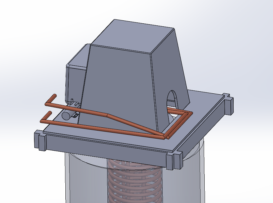
While the build team continued to work on ensuring proper flow, the remote student worked on modeling the external pipes they were using to connect the internal heat exchangers to the pump, reservoir, and blower.
Water Flow Test Video
The above video shows the team's first proper test of the full water circulation system. It mainly focuses on the flow into the reservoir, which is a necessary component of the system used to prevent the pump from running dry. It also shows the pump and exterior piping components of the liquid heating loop.
Air Flow Test Video
The above video was recorded during the team's first main air flow test of the day. It shows the use of an anemometer to verify that the blower is functioning properly. During this test, the anemometer recorded an air speed of 1.1 m/s.
Liquid Heating Test Video
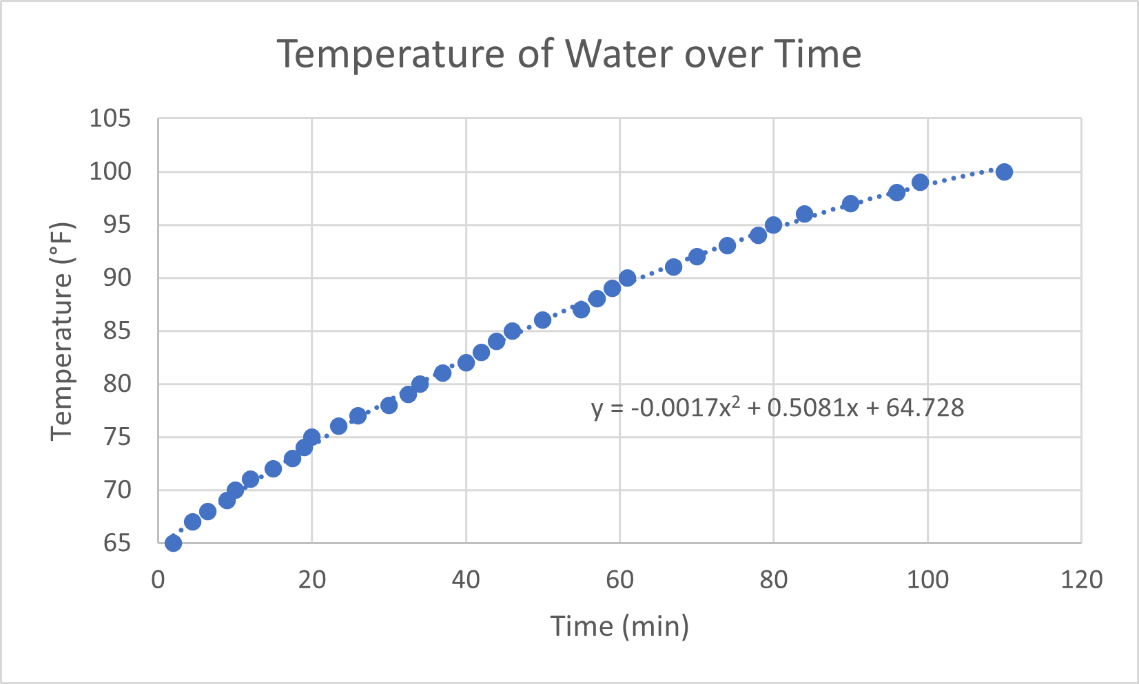
After the team had verified that both the liquid and air circulation networks were functional, they moved on to testing the heating tape and its ability to heat the liquid in the reservoir and heat exchanger. To do this, they ran the pump and turned on the heating tape, checking the temperature of the reservoir with a thermocouple/Arduino data acquisition system. They recorded this data to provided clear demonstration of how the temperature of the water changed over time.
Reservoir Temperature Plot
Shown above is a plot of the reservoir temperature with respect to time, with the data gathered by the Arduino system shown. The plot demonstrates that the temperature increased steadily over time, following a 2nd order polynomial fit. Note that the test was ended early due to time constraints.
According to the plot, temperatures in the heating loop should keep increasing until they reach approach a ceiling defined by heat losses in the system. In the future, the team intends to perform a similar analysis over a longer period of time (8 hours), to determine this ceiling and the length of time needed to approach it. Future tests will also involve a completely full tank, which should create a more accurate representation of the system's intended operation.
Build Day Six: Airflow Testing (3/6/21)
The sixth formal build day focused on adapting the pump and blower to push water and air through their respective heat exchangers, and determining the optimal configuration for both systems.
Click to Expand Gallery
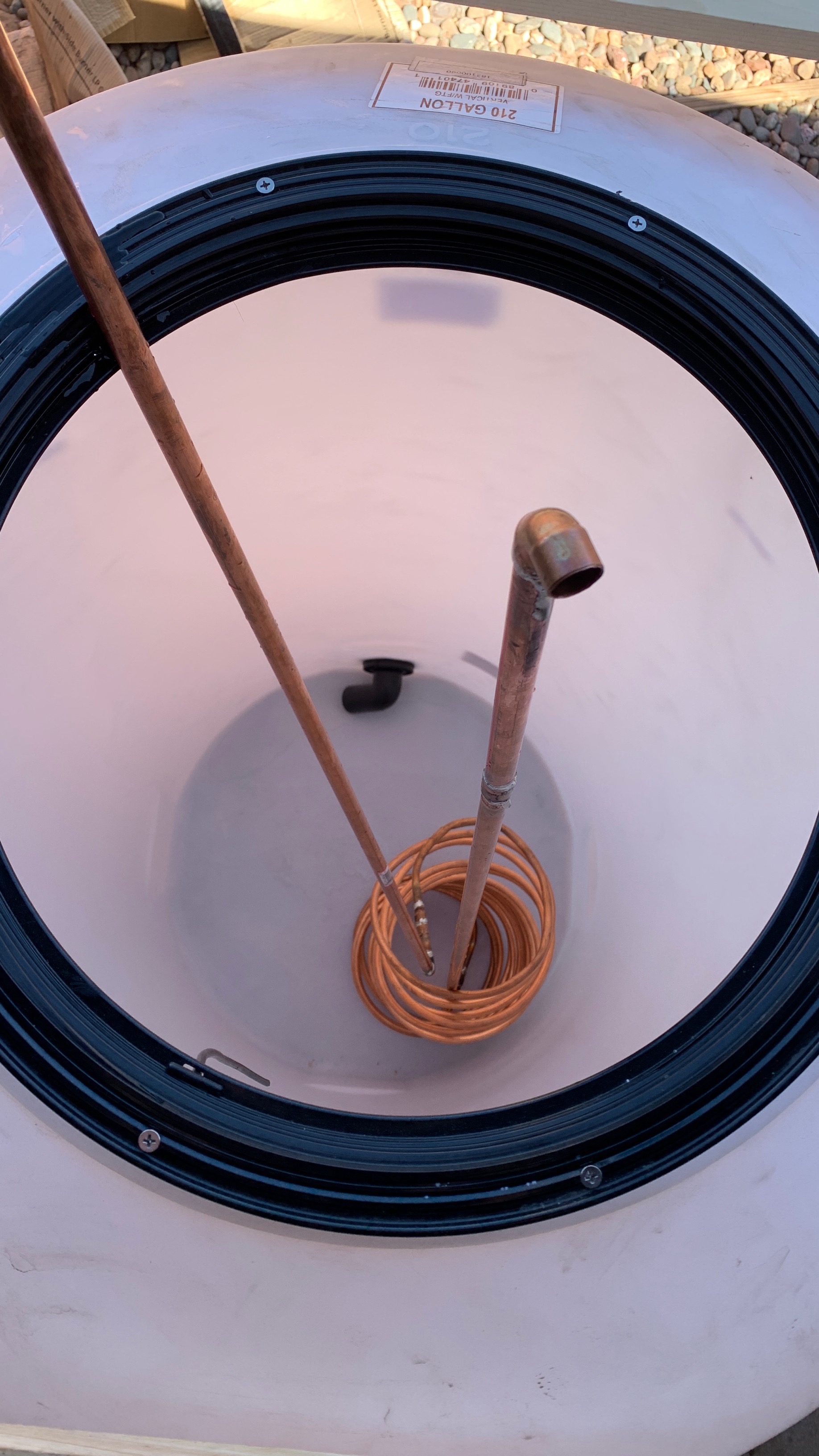
Flow Test Heat Exchanger Placement
Prior to beginning the flow test, the team placed the coiled liquid-to-liquid heat exchanger in the tank.
Heat Exchanger Flow Test
After the heat exchanger had been placed in the tank, the team used their pump and reservoir setup to test the flow rate of water through the system, to great success.
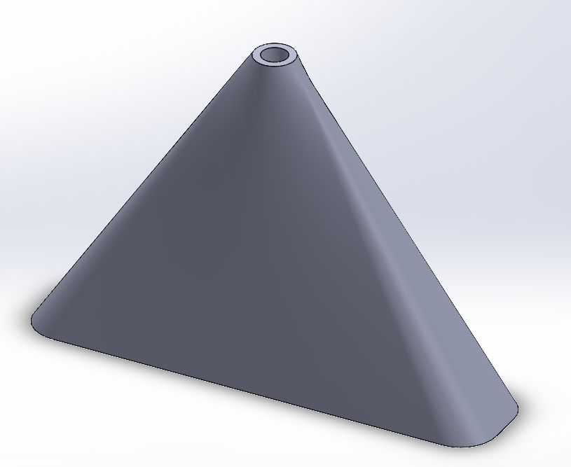
Blower Adapter
In order to use the blower purchased for the liquid-air heat exchanger, the team had to model and print an adapter to connect the blower to the pipe network.
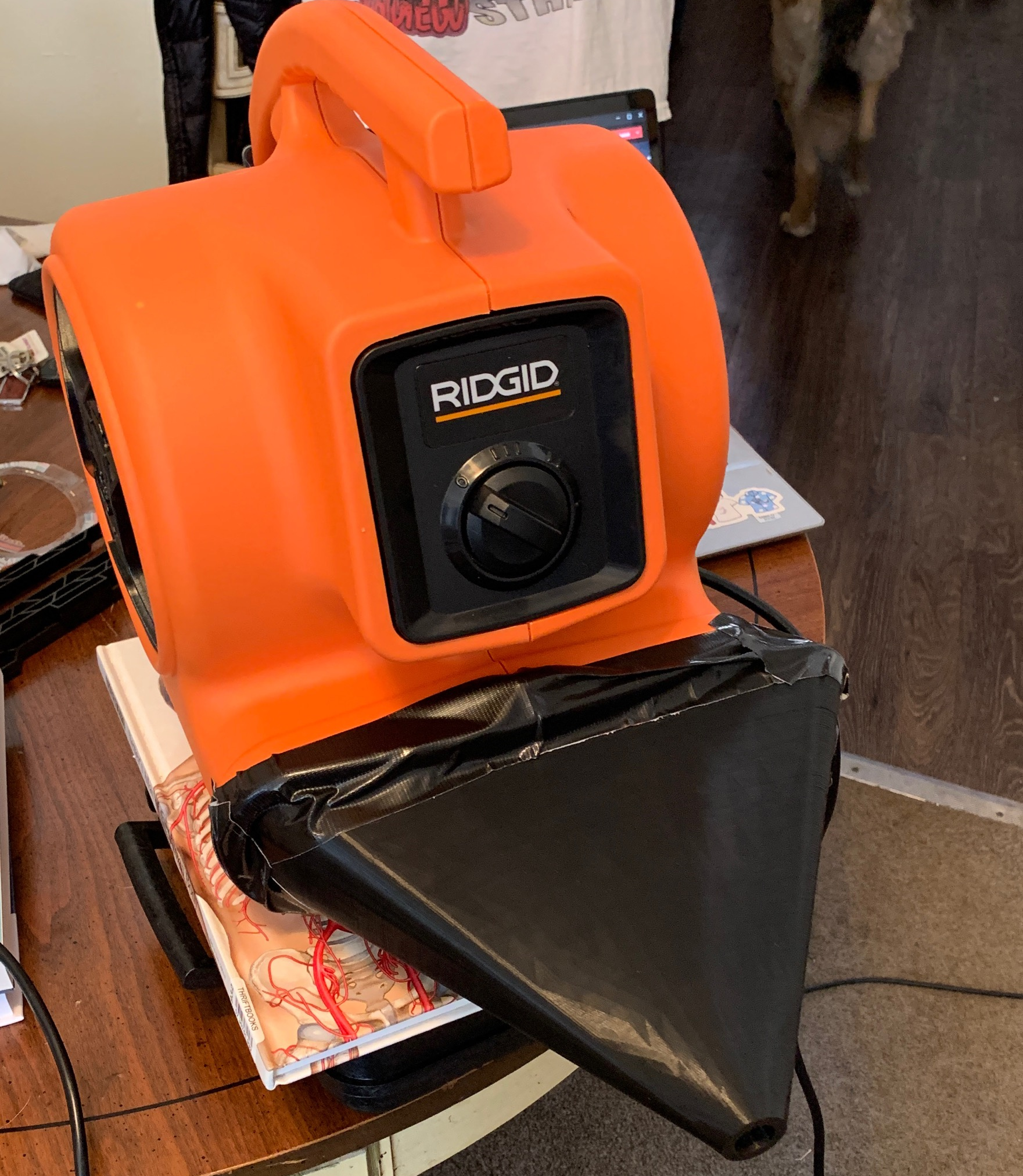
Adapted Blower
After the adapter had been modeled, it was 3D printed using the NAU maker lab and applied to the blower, as shown.
Build Day Five: Platform Construction Day (2/27/21)
The fifth formal build day was focused on the construction of the tank cap and modifications of the lid. The team also performed early tests to examine the integrity of the heat exchangers.
Click to Expand Gallery
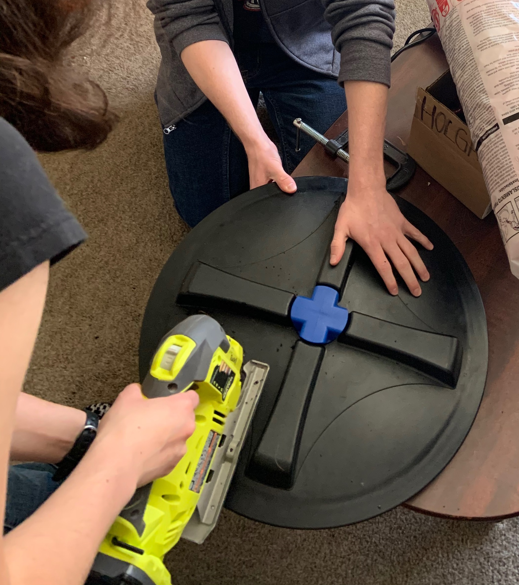
Cutting Lid Holes
Prior to beginning work on the cap, the team used a jigsaw to cut holes in the tank lid to accomodated the heat exchangers.
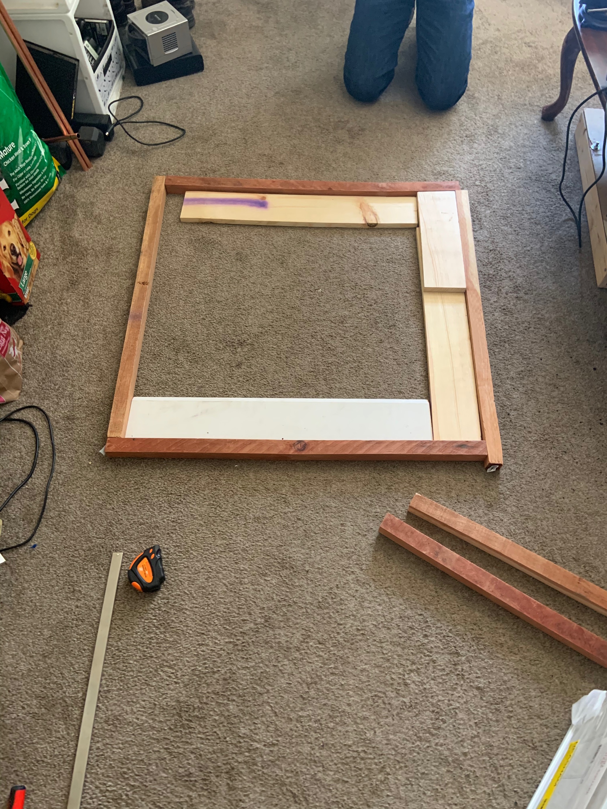
Laying Out the Cap Frame
Once the lid had been adequately prepped, the team began work on the cap by first laying out the frame, in order to establish the base area of the cap.
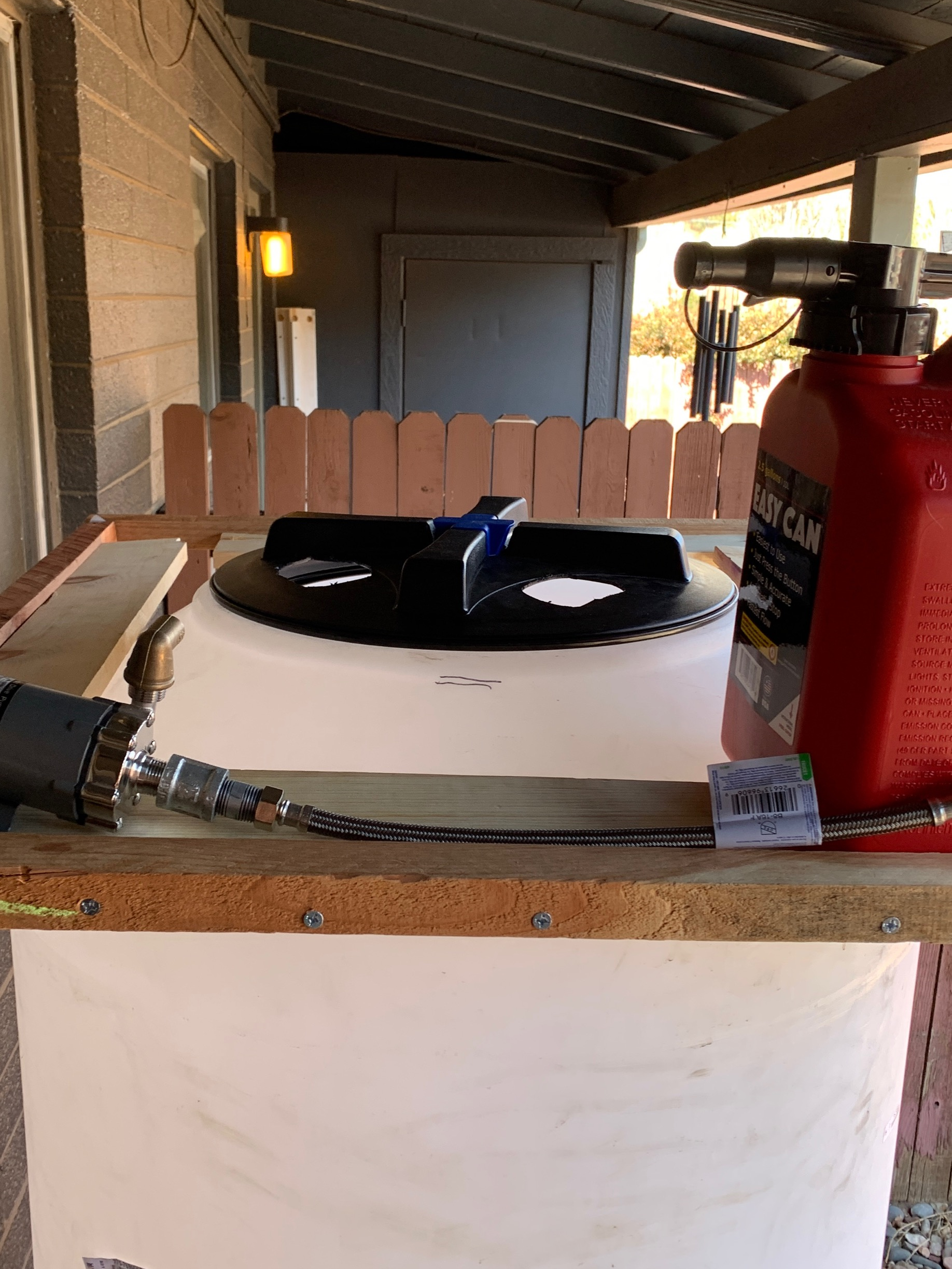
Cap Sizing and Demonstration
After the base of the cap had been joined together as designed, the team set it on the tank to demonstrate how it rests on the sloped tank "shoulders", and to shown that there is ample space for the pump and fluid reservoir.
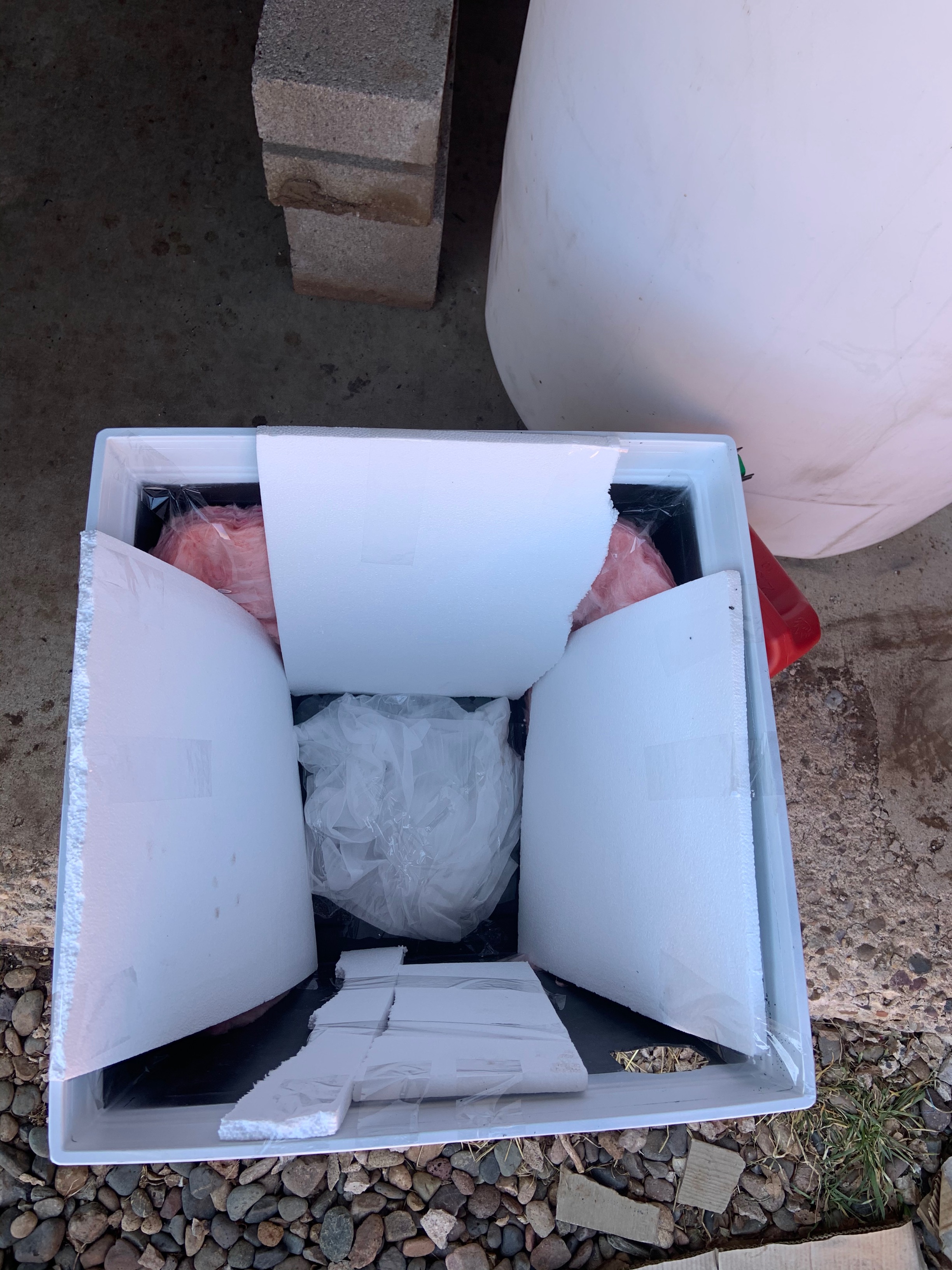
Cap Interior
Once the base of the cap had been created, the team filled the top part with insulation. This section will need to be adequate insulation to prevent significant heat loss through the tank lid.
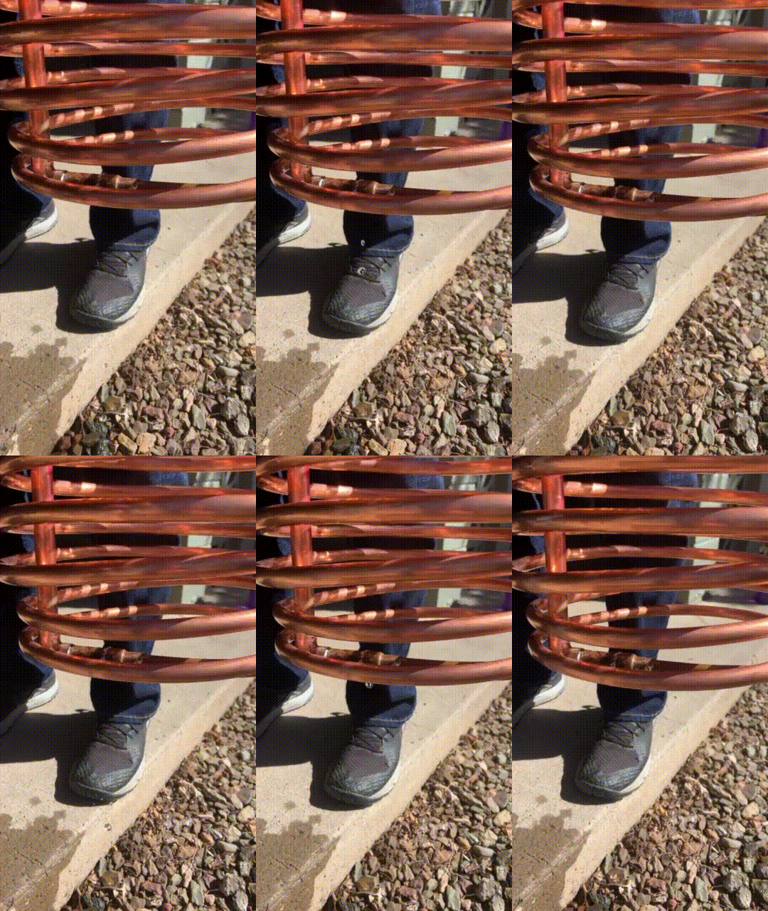
Leak Test
Once cap work had mostly been finalized, the team tested each heat exchanger for leaks by pouring water through the length of the exchanger. The above .gif shows a leak at one of the joints; this was promptly fixed via soldering.
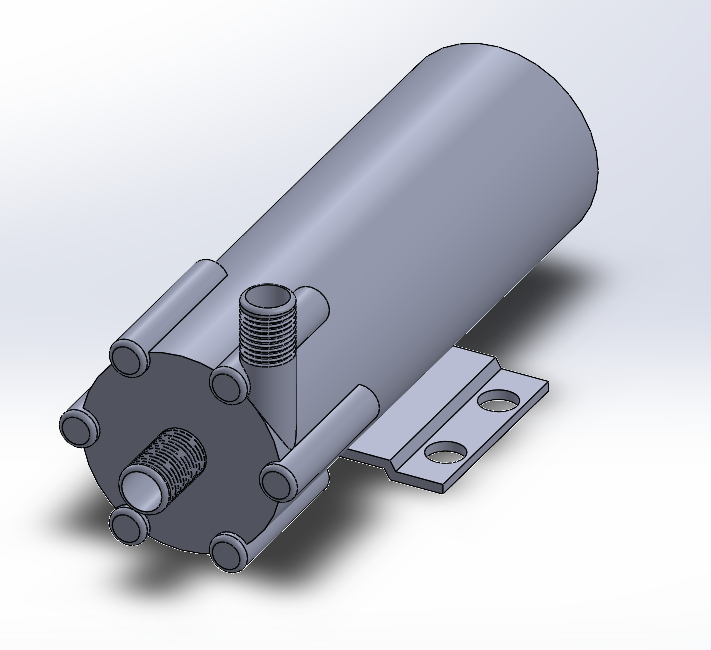
Pump CAD Model
While the team worked on the cap and other tasks, the remote student continued to add detail to the CAD model. In this case, a basic model of the pump was created.
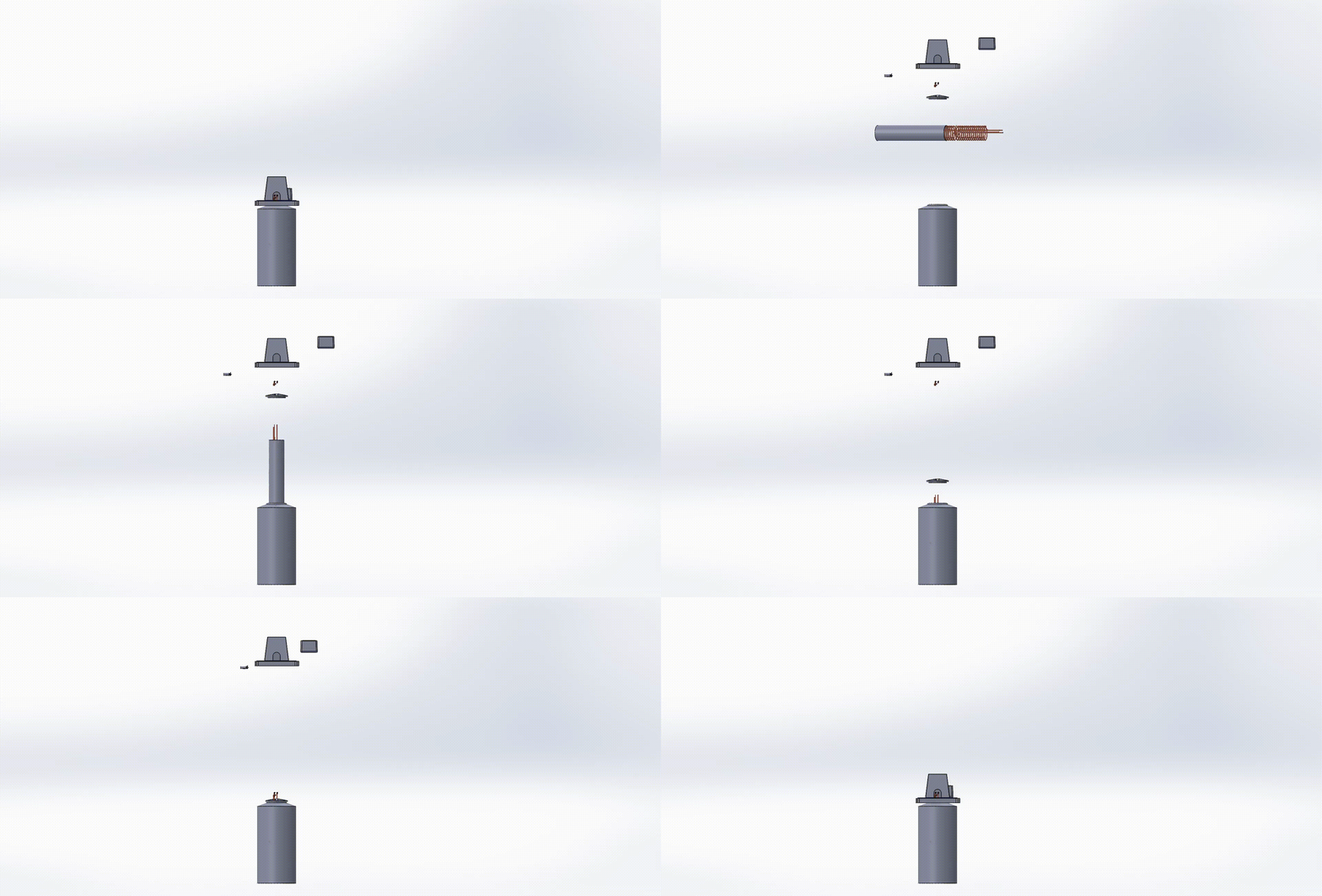
Revised Exploded View
After creating the pump and a rough approximation of the fluid reservoir, the remote student created an assembly view of the device.
Build Day Four: Heat Exchanger Finalization (2/20/2021)
The fourth formal build day focused on coiling the second heat exchanger, soldering extensions, and preparing the full Heat Exchanger Package.
Click to Expand Gallery
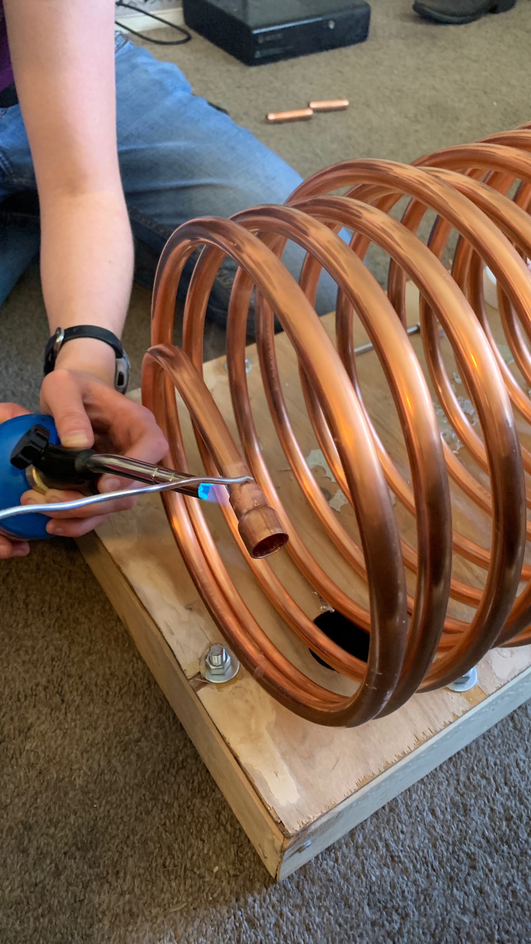
Coiling and Fitting Second Heat Exchanger
The use of a blowtorch made coiling the second heat exchanger much easier than the first. It was also used to solder the necessary fittings to the pipe.
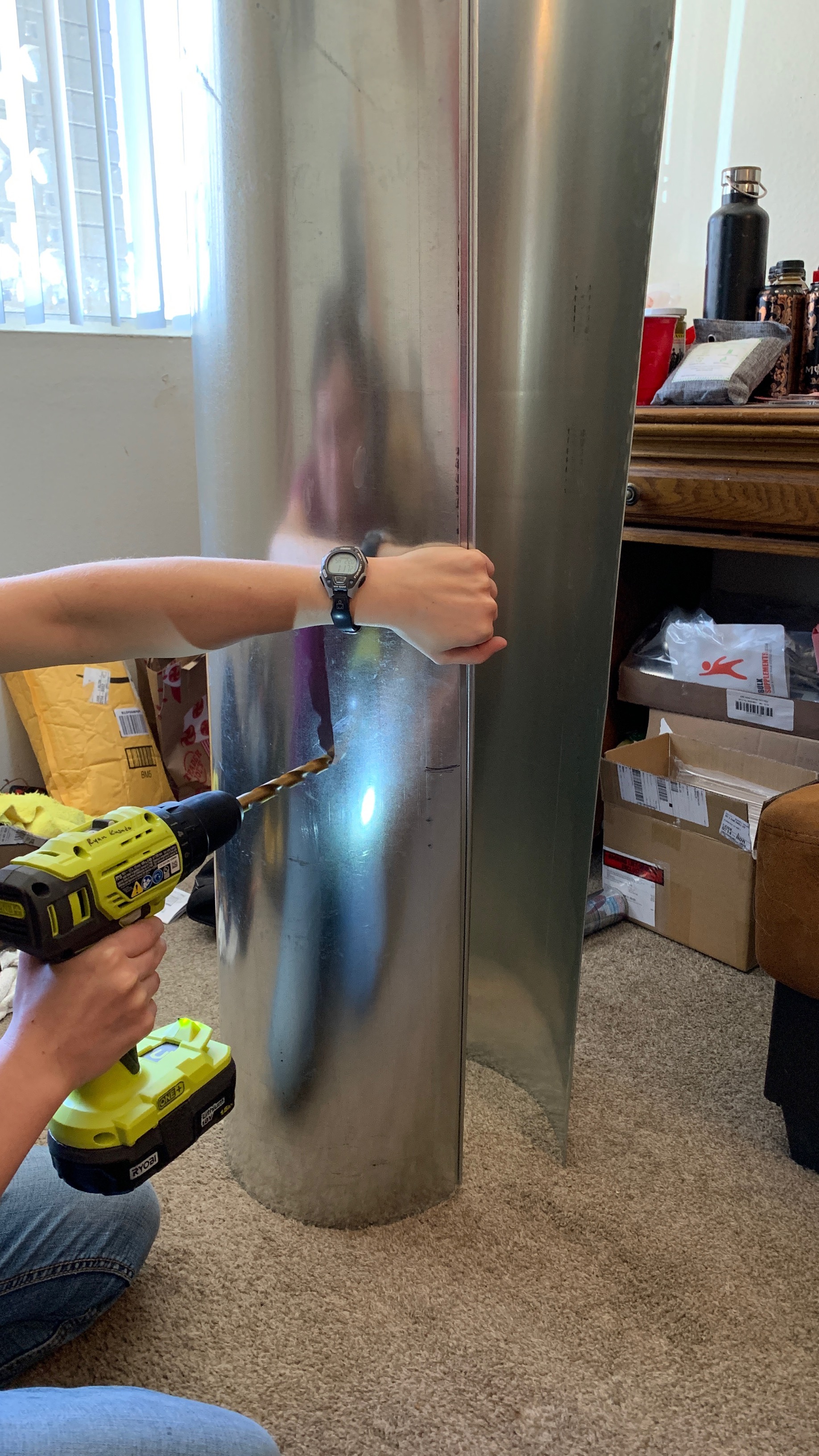
Drilling Duct Holes
Once the heat exchangers were completed, the team began drilling holes in the side of the duct, which will be used to mount the heat exchangers and hold the assembly together.
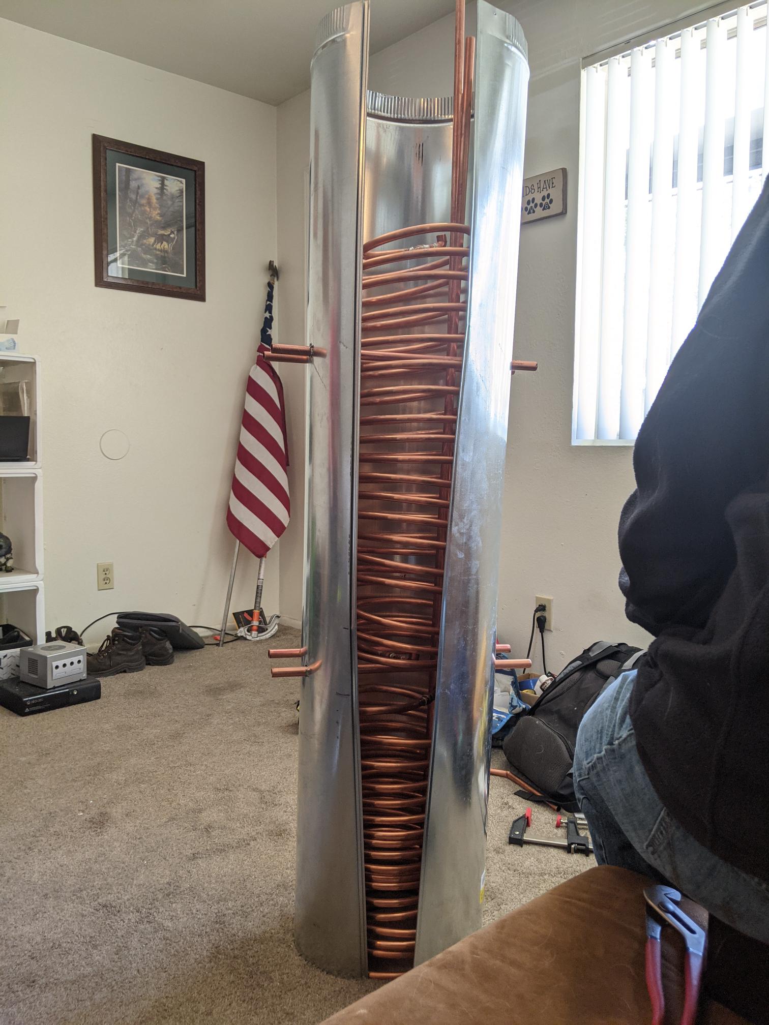
Heat Exchanger Package
After drilling the holes through the duct, the team was able to use copper pipes as crossbeams, both to hold the duct together and to support the heat exchanger coils within the duct.
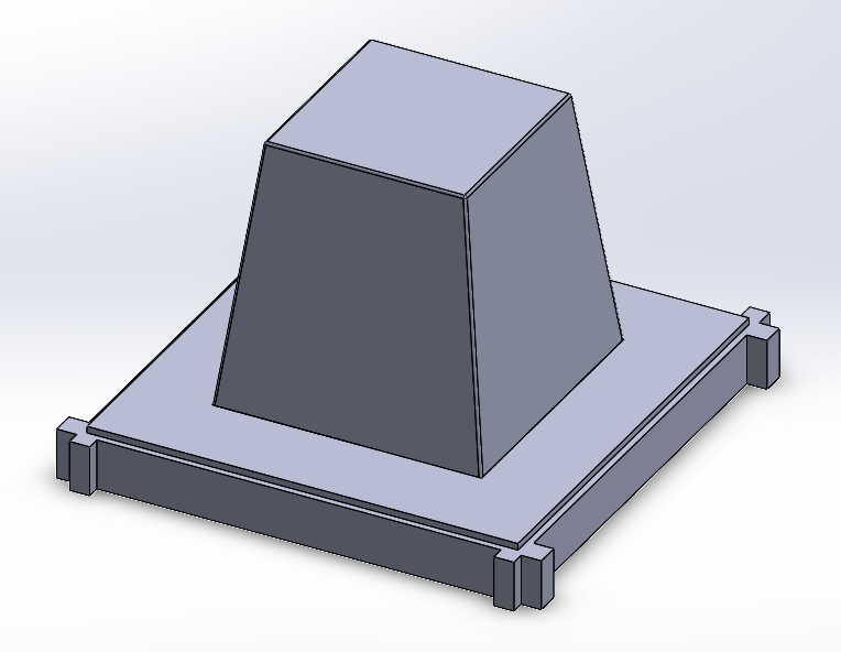
New Cap
While the team worked on completing the heat exchanger, the remote student worked to implement changes in the physical design implemented when parts were purchased. This mainly included the cap, which was reshaped to reflect a new box and platform size.
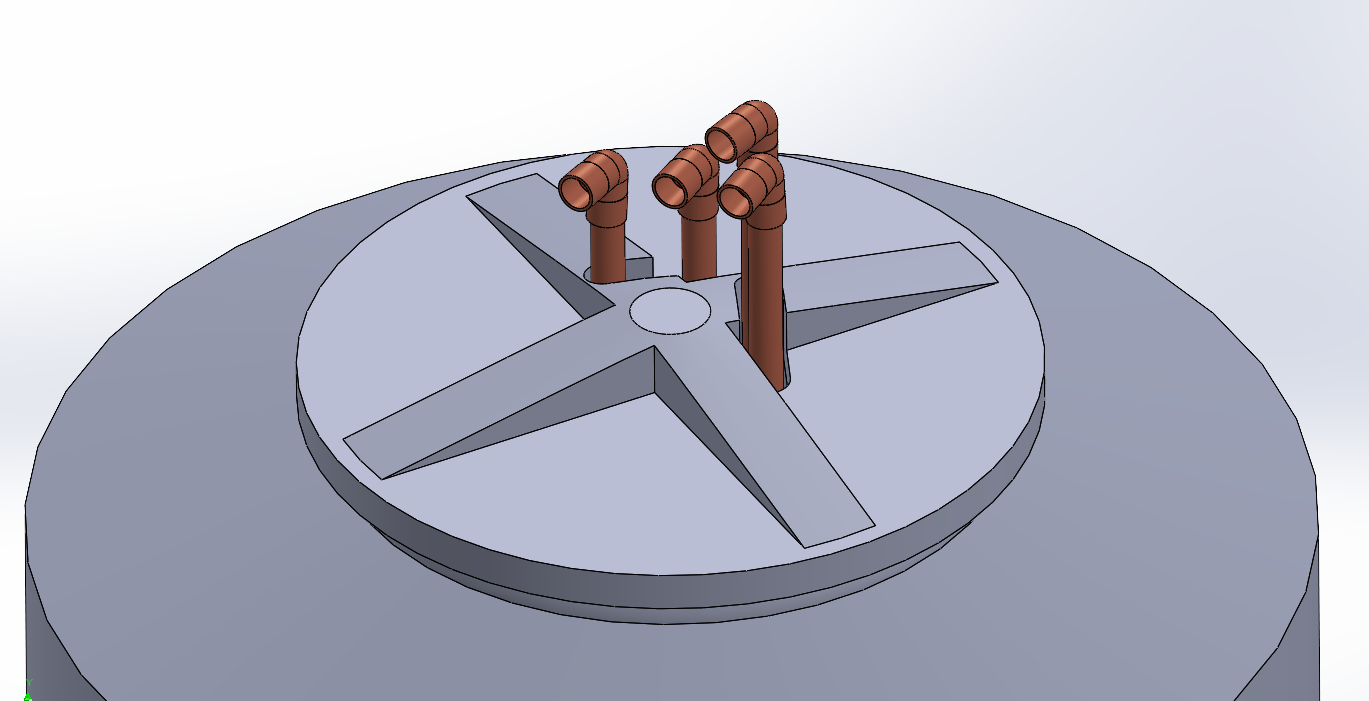
CAD Improvements
In addition to creating a new cap model, the remote student also worked to update the piping and lid, to mock up how the heat exchangers might pass through the tank cap.
Build Day Three: Heat Exchanger Soldering and Extension (2/17/2021)
The third formal build day focused on soldering together the final pipe components of the first heat exchanger.
Click to Expand Gallery
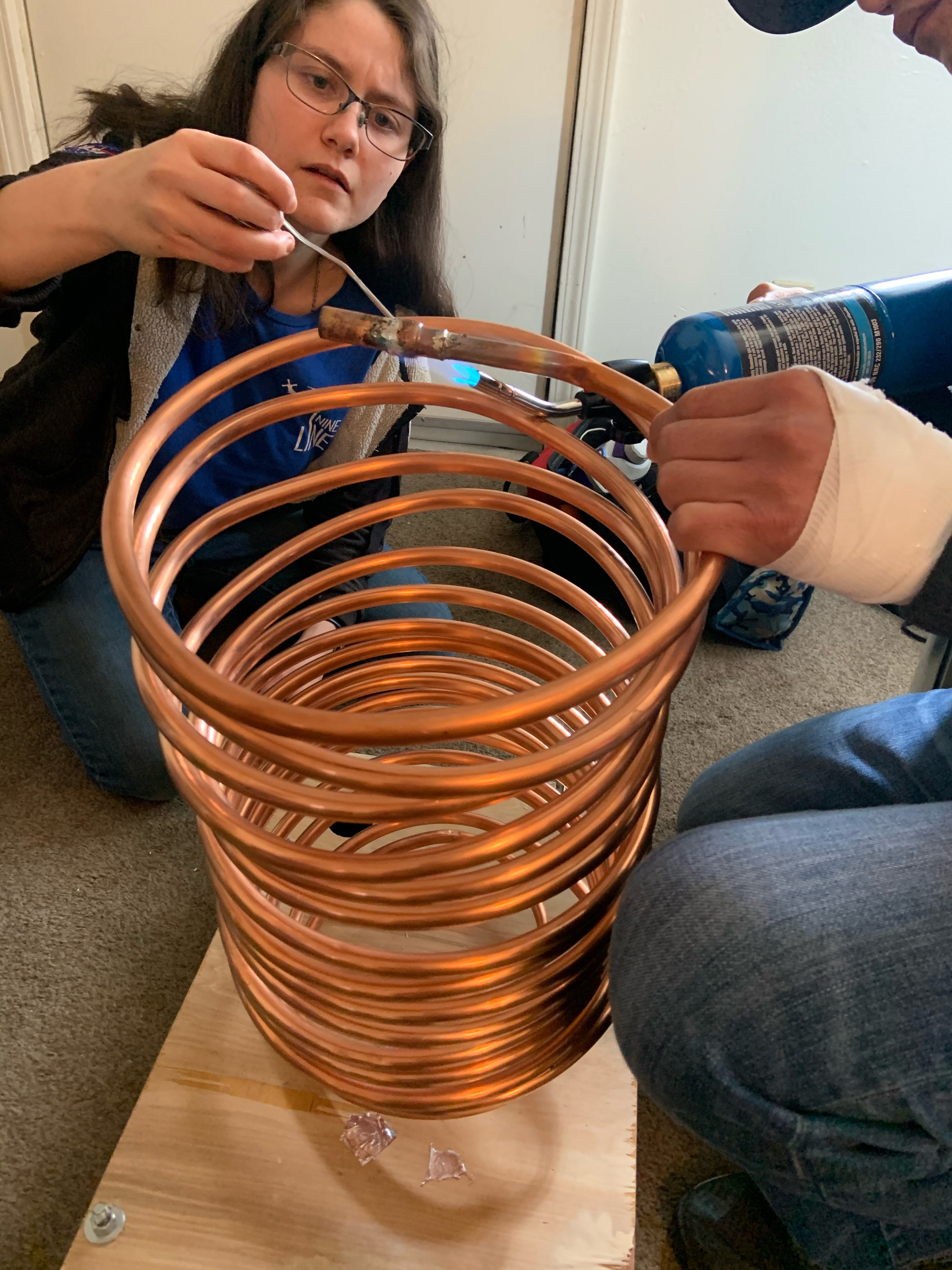
Soldering Pipe
To join pipe sections and fittings, the team used soldering wire, flux paste, and a small propane torch to solder the pieces together.
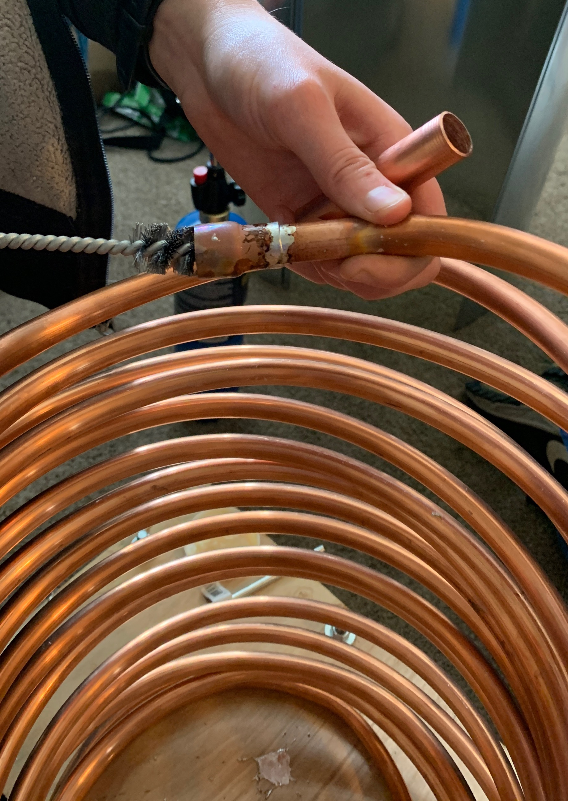
Pipe Brushing
After soldering pipe fittings onto the coil, the team used a stiff wire brush to remove any remaining debris from the soldering process.
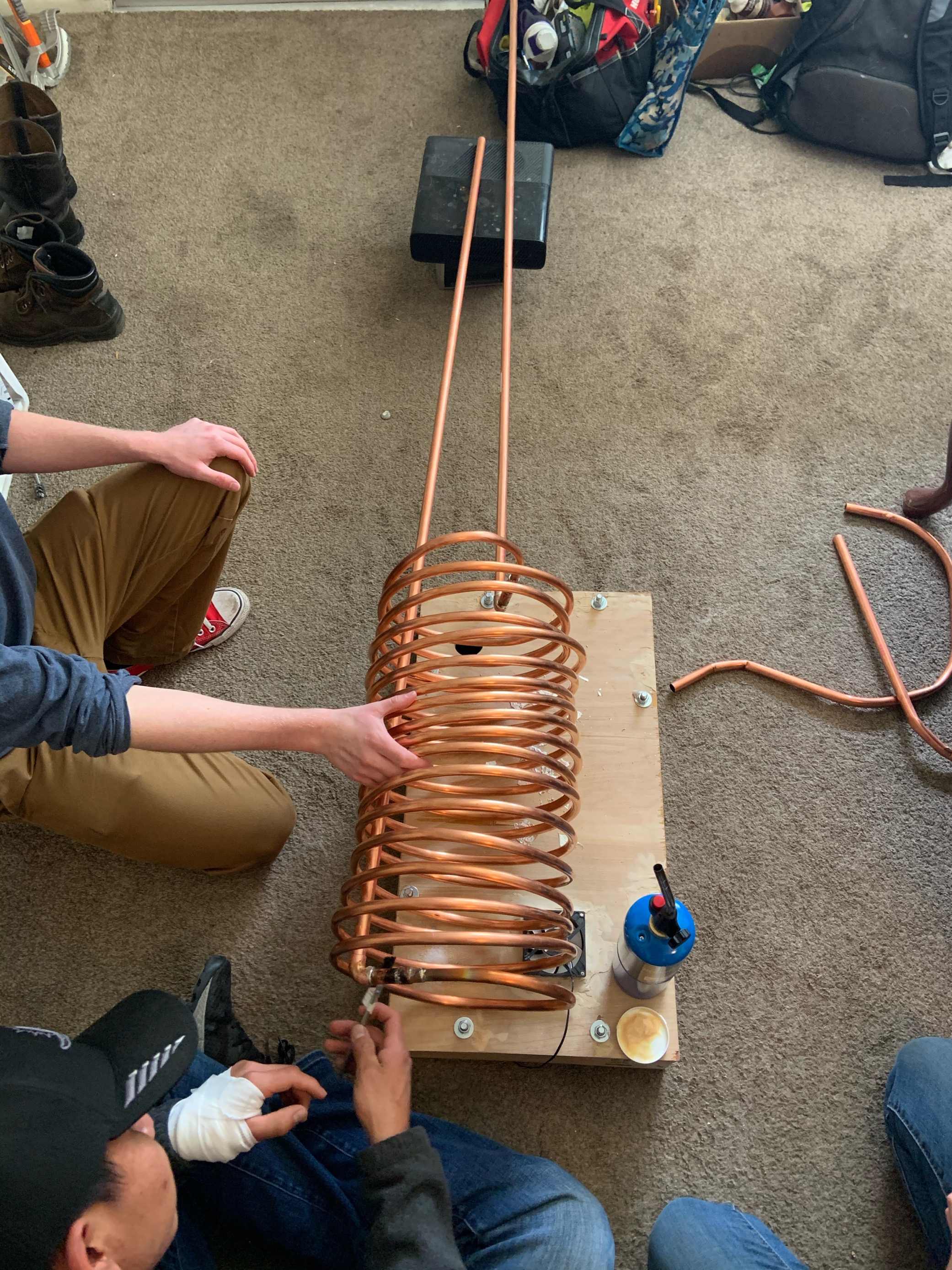
Extension Installation
After the necesary fixtures had been soldered into place, the team installed the extension pipes that will pass through the lid. This was done with the same soldering process and materials.
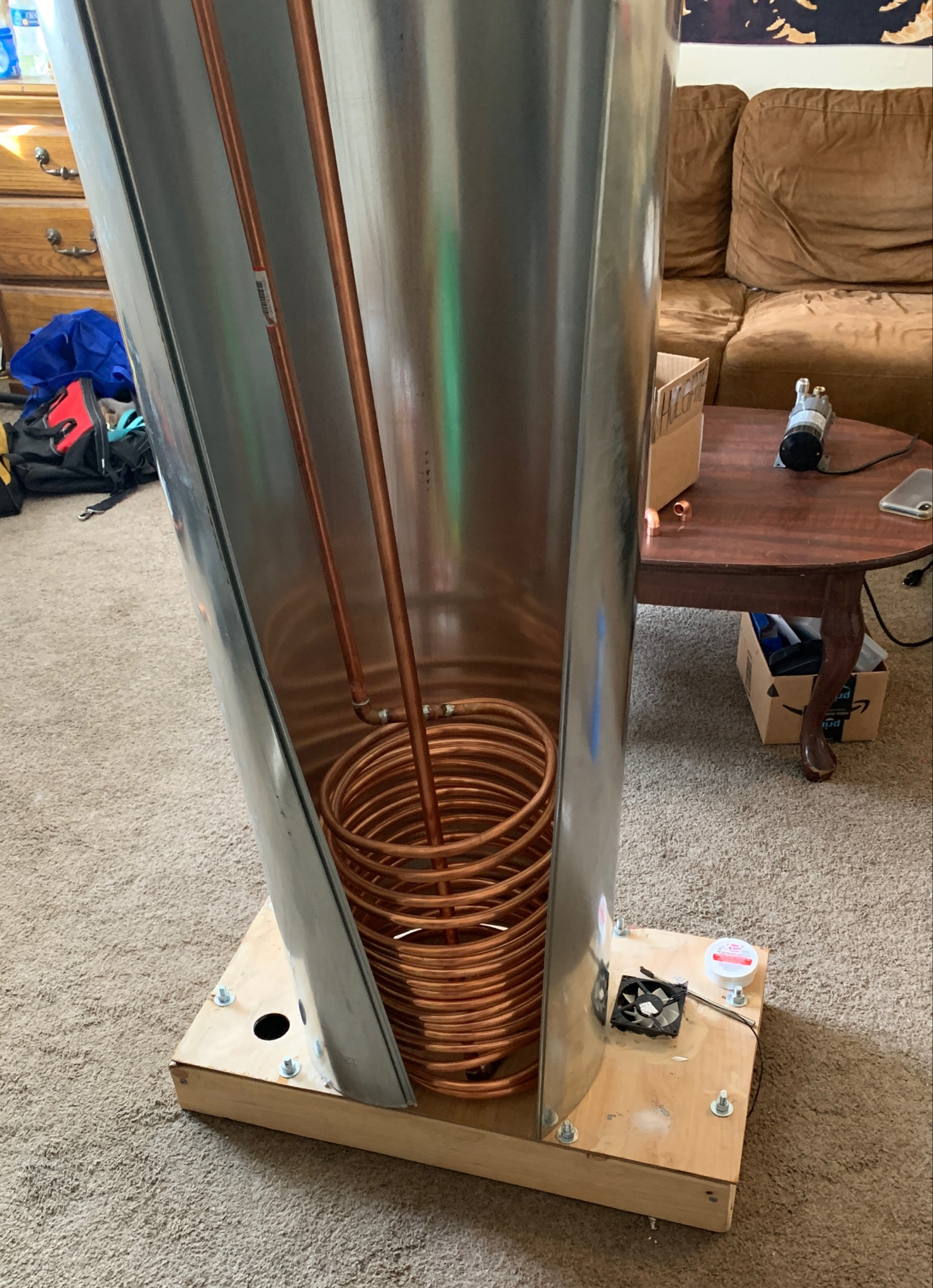
Duct Fit
After the team finished with the extensions, they checked to ensure that the coil could still be nested in the duct, and that the extensions were long enough. It was determined that they would be long enough so long as the duct is appropriately spaced from the bottom of the tank.
Build Day Two: Heat Exchanger and Duct Work (2/13/2021)
The second formal build day focused on finalizing the design, in addition to sizing the first coil for the duct.
Click to Expand Gallery
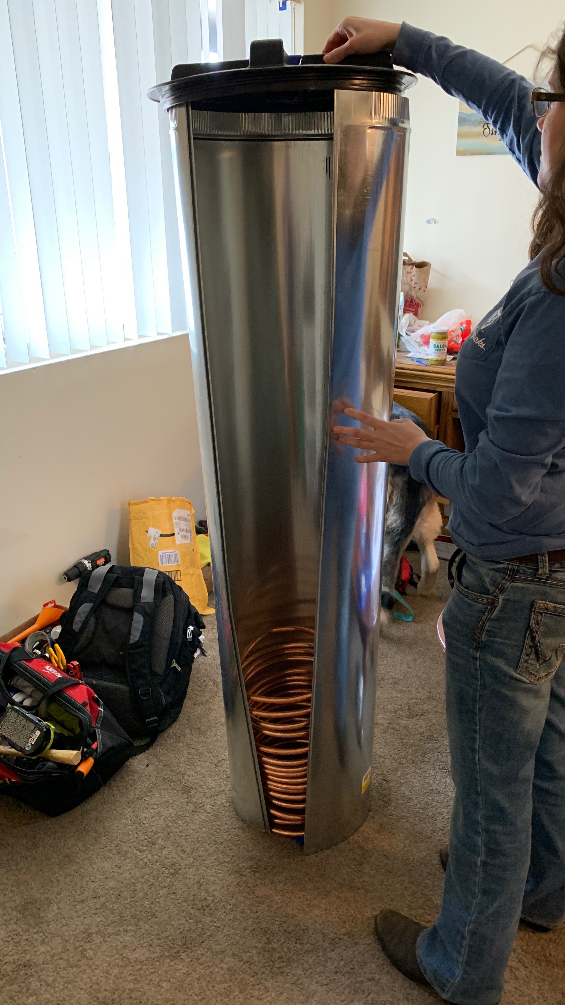
Duct Fitting
For the purpose of creating a singular, modular heat exchanger package that could be easily installed or removed from the tank, the team sized the two heat exchanger coils for fitting into a 12 inch duct.
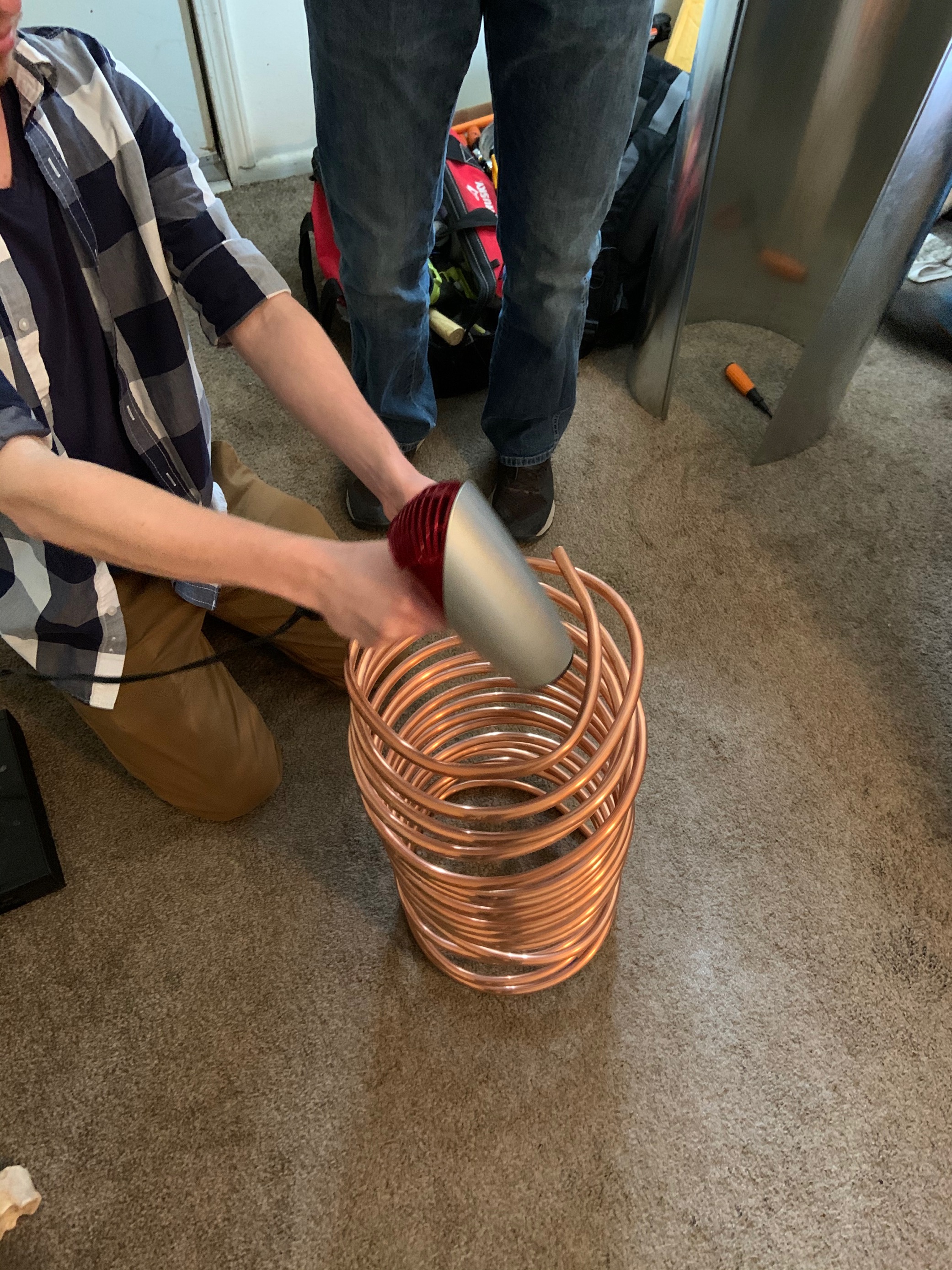
Coil Heating
In order to facilitate heat exchanger shaping, the team heated the pipe, making it more malleable and easy to shape. This made adjusting the pipes much easier.
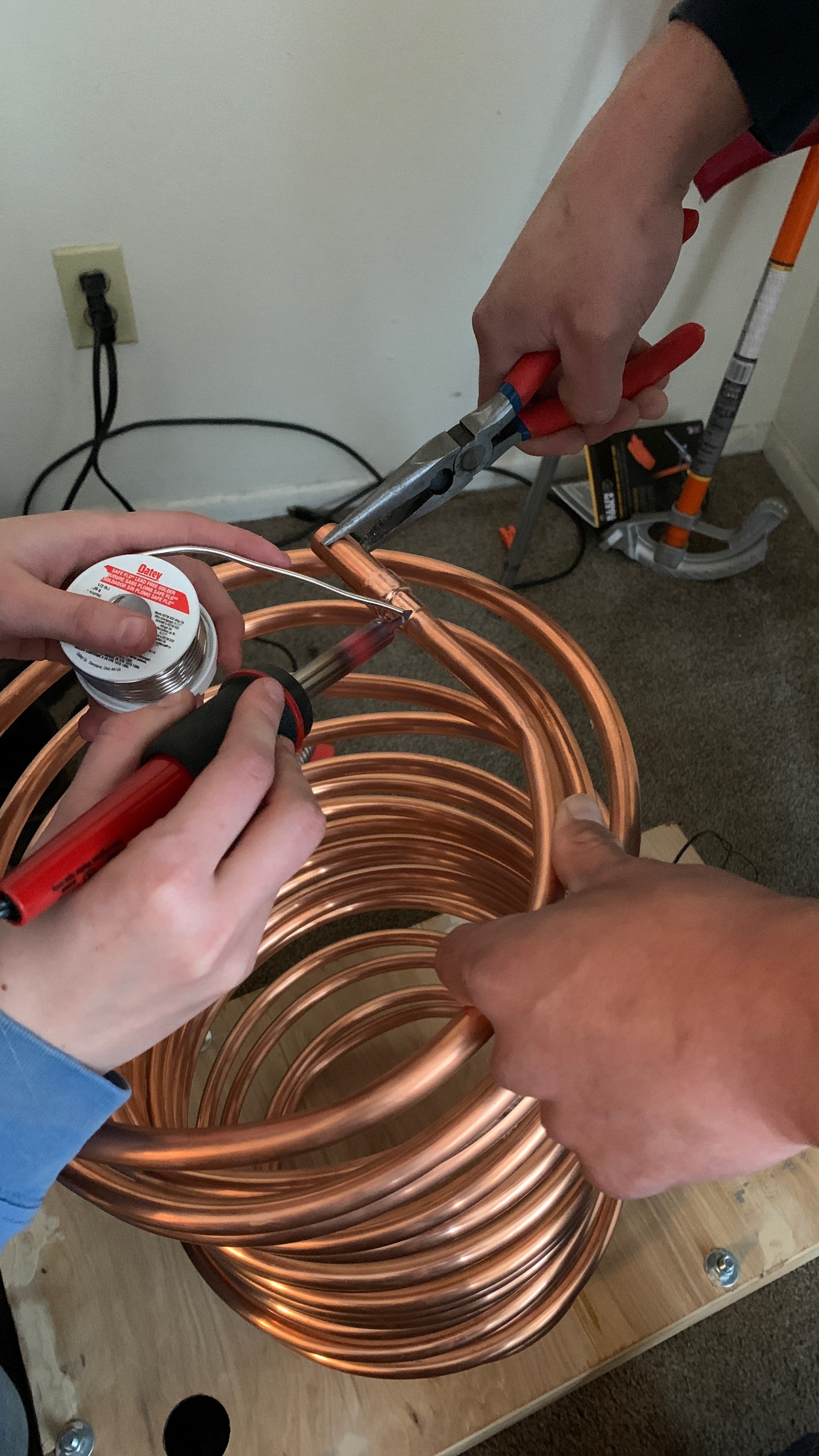
Soldering
In order to connect heat exchangers to other pipes, the team used soldering wire and an iron to weld them together. They found that the soldering iron provided insufficient heat, and that a torch would be needed.
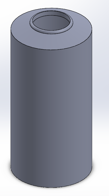
CAD Modeling
While the rest of the team was working on the second heat exchanger, the remote student worked to update CAD models, and to mock up a design for cap for the tank, that could support necessary tank infrastructure.
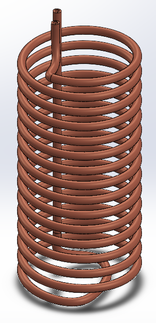
CAD Modeling (Continued)
This is the revised model of the heat exchanger, with pipes running up through the center.
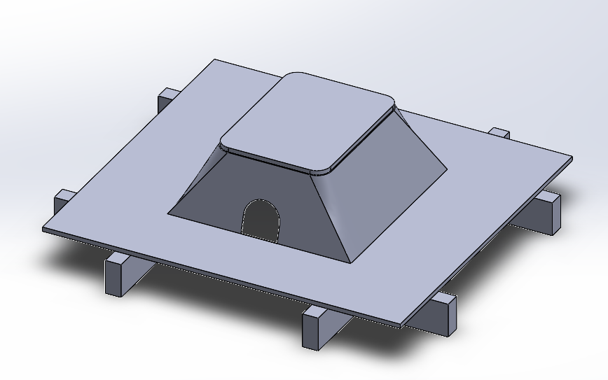
CAD Modeling (Continued)
The remote student also created a mock-up for a cap that could sit on the tank, used to support necessary infrastructure for pumps and tank heating.

CAD Exploded View Collapse
Once updated CAD models of the tank, heat exchangers, duct, lid, and cap were created, an assembly was made. Above is a .gif of this assembly showing how the parts fit together. A CAD package of this is available on the documents page.
Build Day One: Heat Exchanger Coiling (2/6/2021)
The first formal build day was focused on the construction of the liquid to air heat exchanger. This was done by bending soft copper pipe into the desired shape.
Click to Expand Gallery
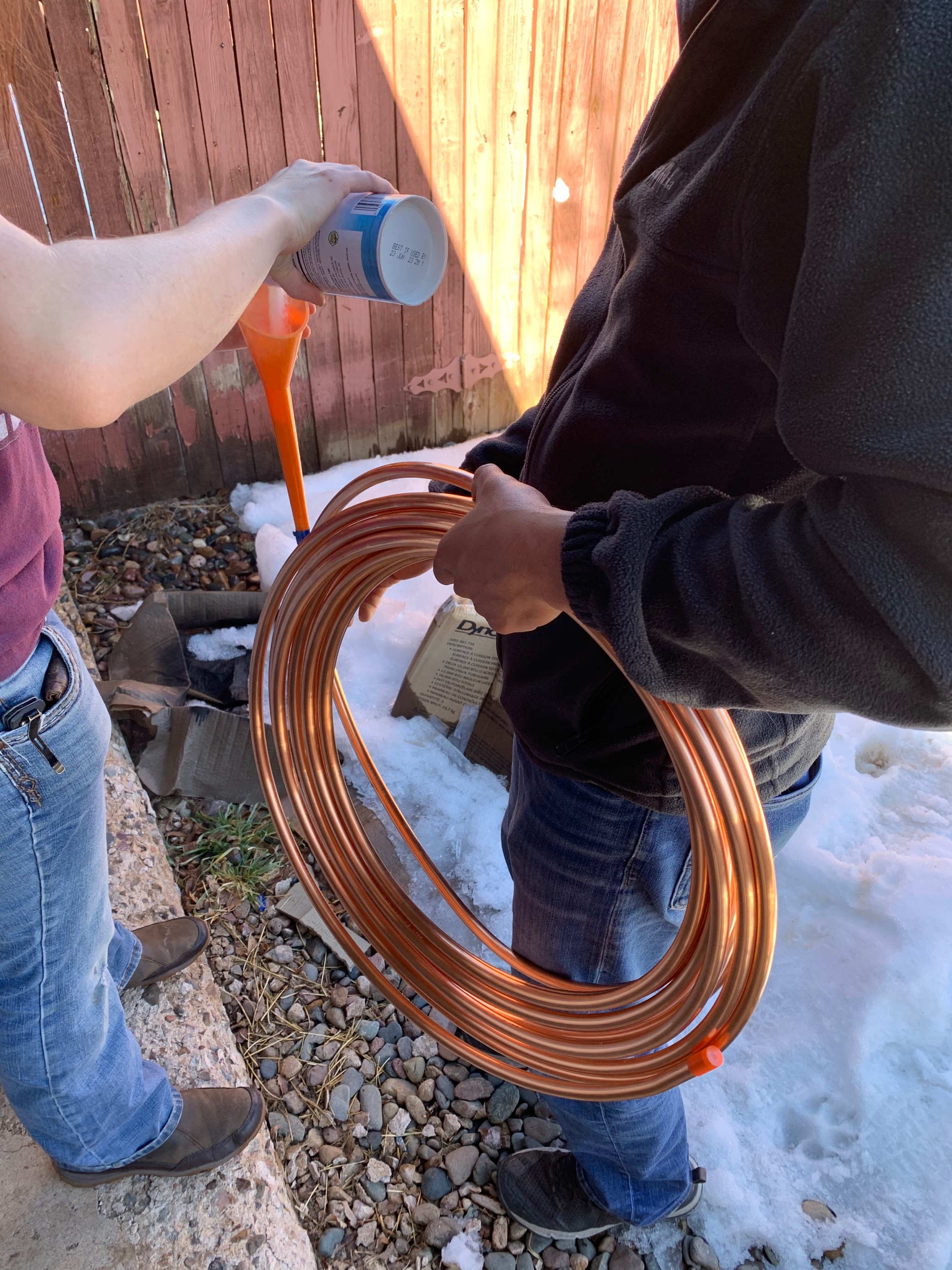
Pouring Salt
Prior to bending the pipe, the team started by pouring salt into its entirety. This was done to prevent the pipe from kinking while the team bent it into shape.
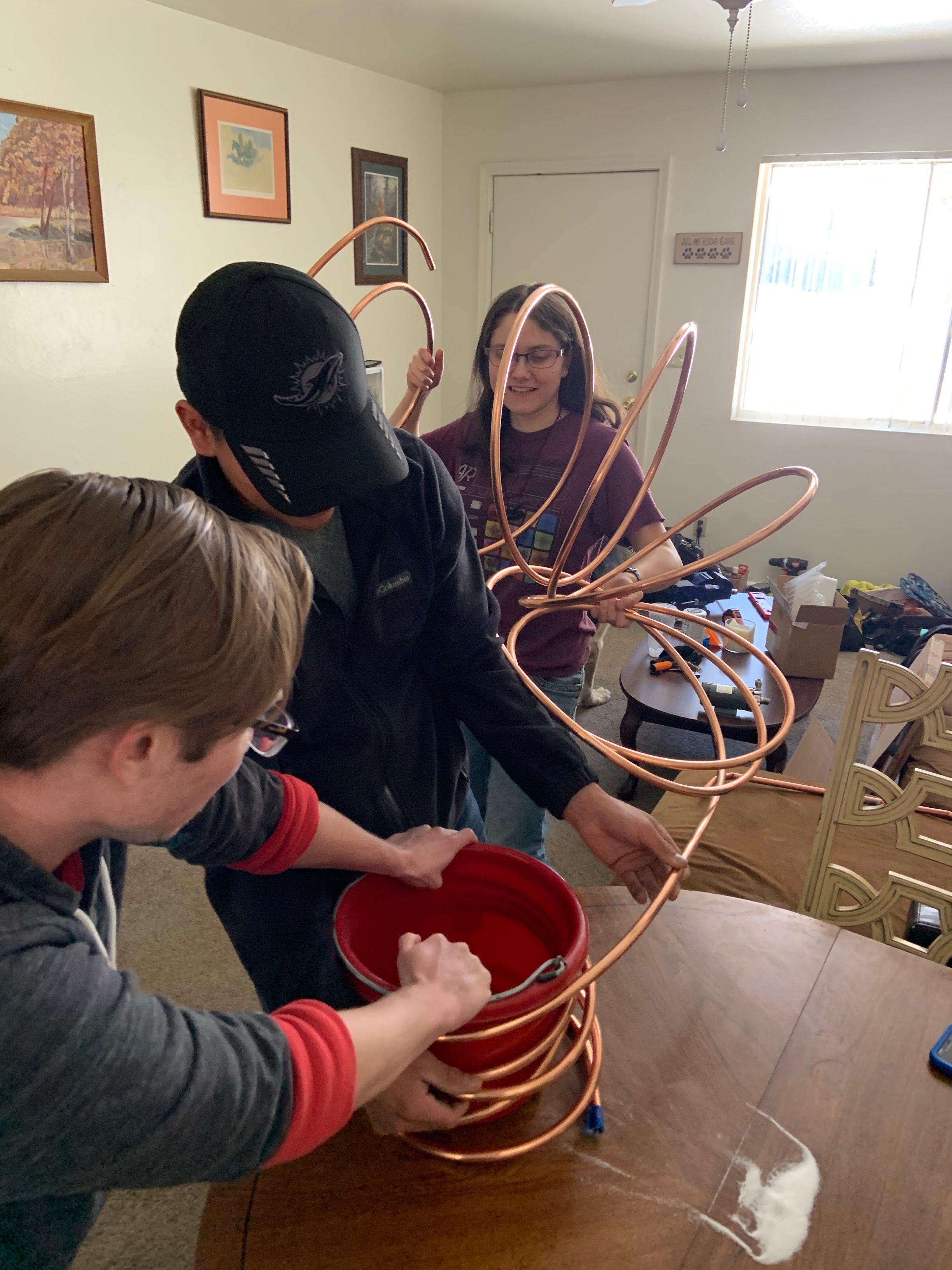
Coiling Starts
In order to obtain the desired coil radius, the team began by uncoiling the larger, original loop of pipe and winding it around a small bucket.
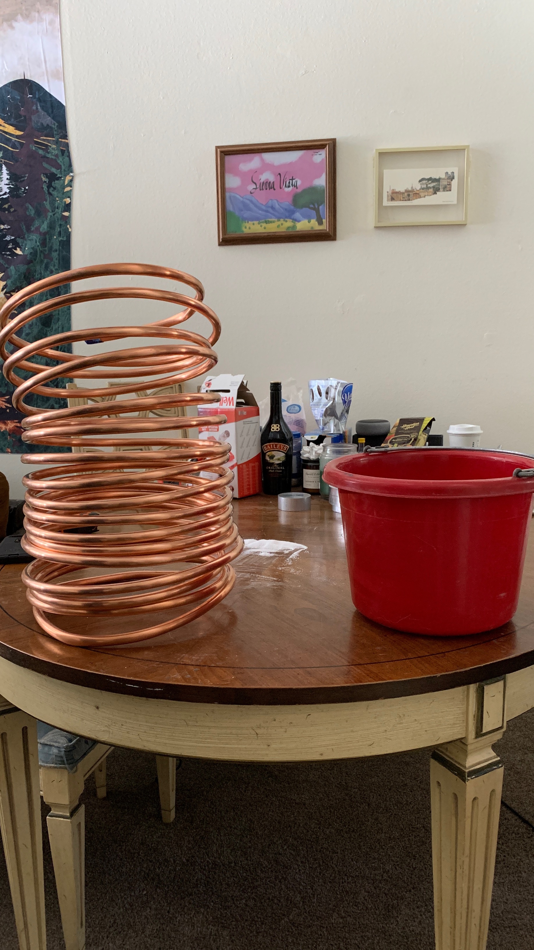
Finished Coil
Once the entirety of the coil had been reduced to the desired diameter, the team removed the bucket. The coil is now sized appropriately for use in the tank.
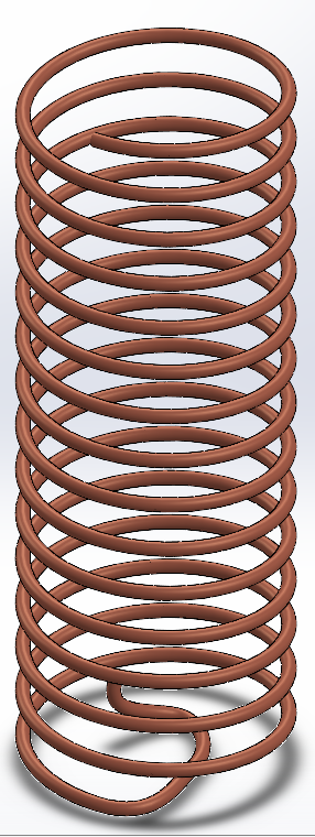
CAD Model
While the team in Flagstaff was working to shape the coil, the remote student created a CAD model to match the revised design, shown above. Additional detail will be added as the build progresses.
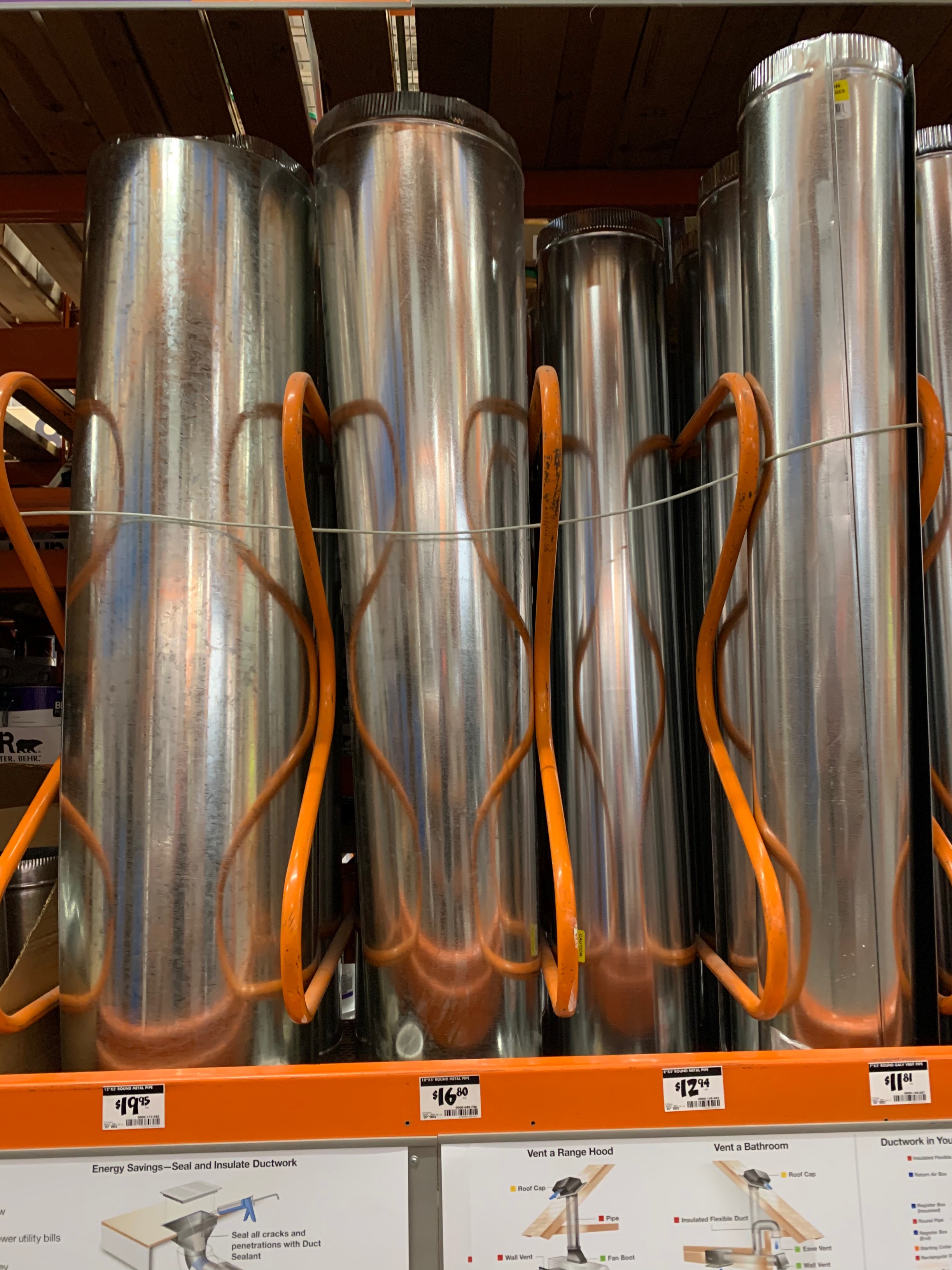
Duct Purchasing
After constructing the air to liquid heat exchanger coil, the team found an appropriately sized duct to house it at The Home Depot.
Design Process Images (Semester 1)
These images communicate key aspects of the design decisions made prior to prototyping.
Click to Expand Gallery
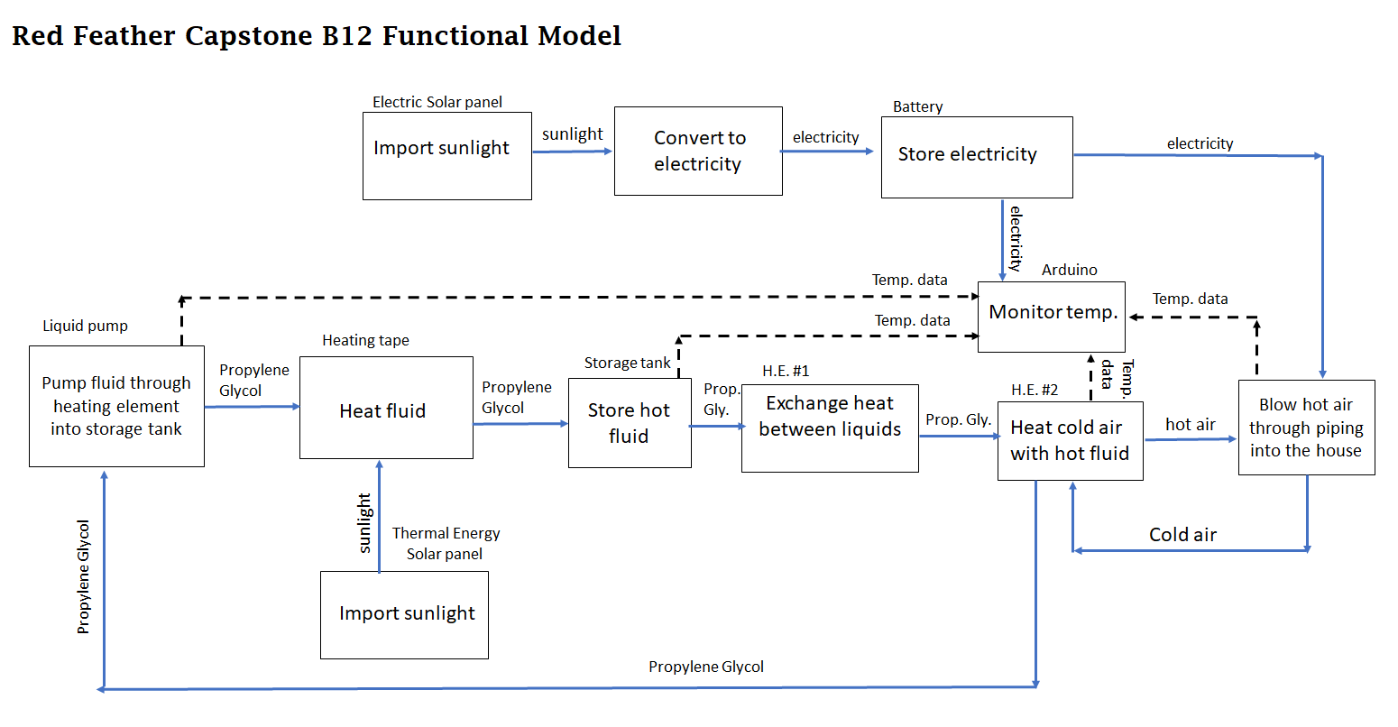
Functional Model
This functional model details the function of the device.
House of Quality
This is the House of Quality for the design, as of December 2020.

Image 3
This is a "large image" placeholder.