Final Design Details

This page contains information on the design selected by the team for prototyping during the spring semester.


System Schematic:

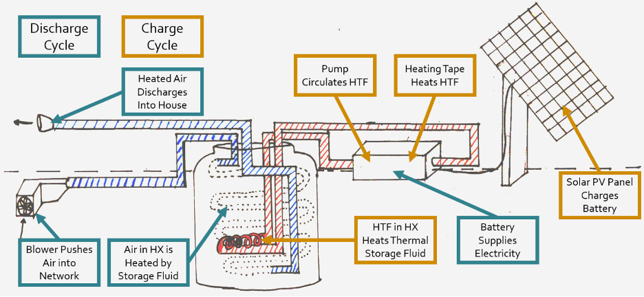
The system goes through two different cycles while in operation, one during the day and one at night. These are distinguished by color in the image shown.

During the day, the system goes through the charge cycle. In this cycle, the pump circulates “cool” heat transfer fluid (HTF) through the heating tape section of fluid heating network, where it is heated. From there, it moves through the pipe network into a fluid-to-fluid heat exchanger (HX) immersed in the tank. Here, heat moves from the transfer fluid to the storage fluid, “charging” the thermal battery. This cycle continues until the tank reaches a pre-determined temperature threshold.

At night, the system goes through the discharge cycle. In this cycle, a blower pushes air from the house into the air pipe network. Here, air passes through the heated thermal storage tank, where it is warmed in a liquid to gas heat exchanger. From there, it flows through the remainder of the pipe network out of the tank, and back into the house. This cycle continues throughout the night, with air speed and heat transfer varying according to the inputs of the control system.

Credit: Noah Kincheloe

CAD Drawing:

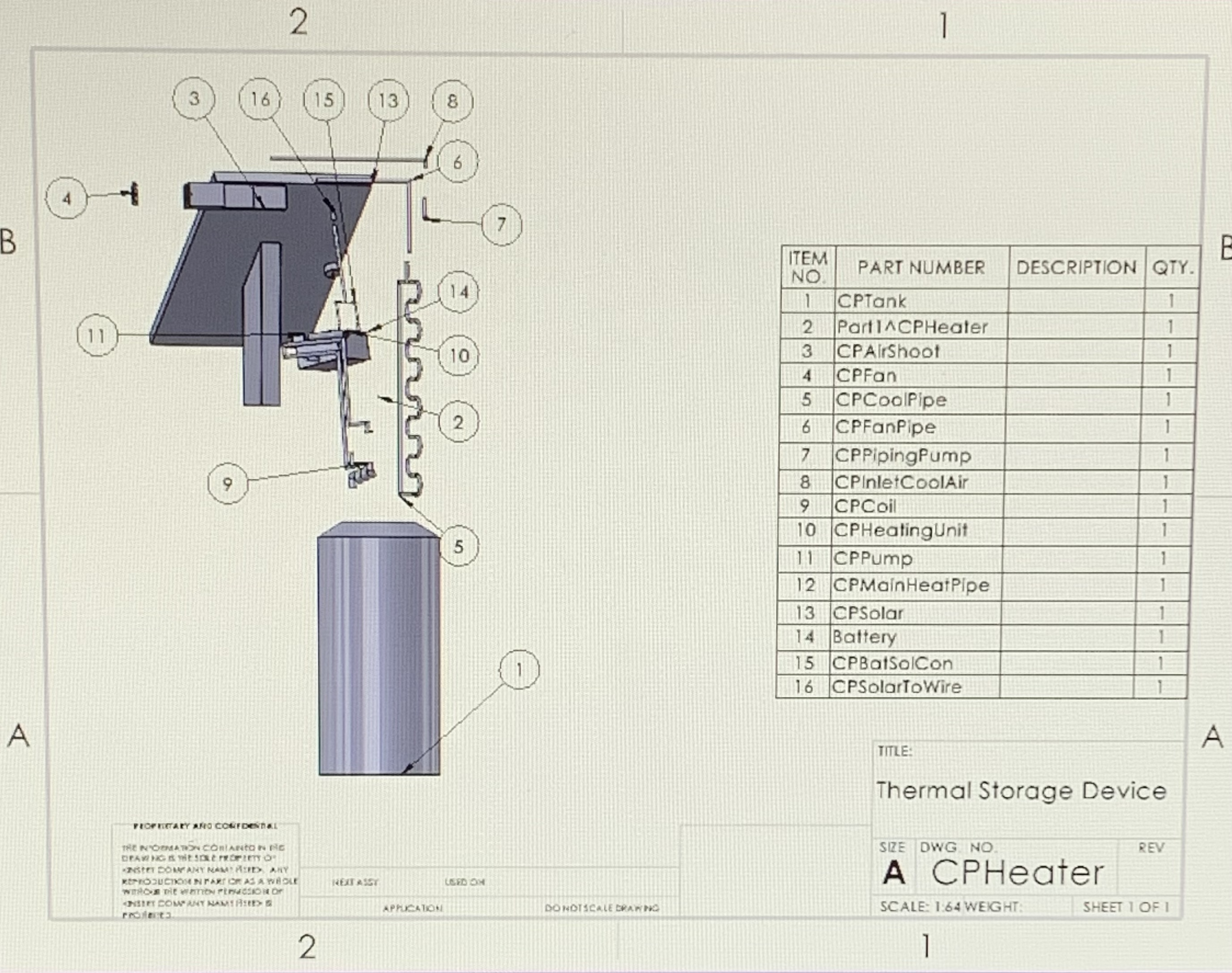
The drawing below is a CAD model of the device. This text is a description of the device/CAD model.
Credit: Wesley Garcia


Major Subsystems

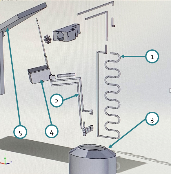
Subsystem 1: Air Pipe Network

This subsystem is responsible for moving the air through the storage device, where it is heated before being delivered to the house. It uses a blower at the inlet of the pipe network to maintain airflow. It only operates when the thermal storage device is discharging.

Subsystem 2: Fluid Heating Network

This subsystem is responsible for moving heat transfer fluid between the heat source and the interior of the tank. The heat source, which is, for the purpose of this prototype, heating tape, increases the temperature of the transfer fluid, which then delivers thermal energy to the storage device. A small, temperature-resilient pump is used to drive this flow. It only operates while the thermal storage device is charging.

Subsystem 3: Storage Tank

This subsystem holds the thermal storage fluid, currently proposed to be a 20% propylene glycol solution for its relative non-toxicity and thermal properties. It heats up while the thermal storage device is charging during the day and cools down as the thermal storage device discharges and heats the house at night.

Subsystem 4: Control System

This subsystem shares a weatherproof container with the battery (part of the final subsystem, the power supply). It uses an Arduino with thermocouples to monitor temperatures at key points in the system and adjusts the diffuser and pump to ensure consistent delivery of warm air during the night and continuous charging in the day.

Subsystem 5

This subsystem is composed of a solar photovoltaic panel and a battery. During the day, the solar panel charges the battery, which is responsible for powering the control system and blower throughout the night.


Credit: Wesley Garcia

Subsystem Diagram

The above CAD image contains a diagram of the full system, with each critical subsystem labeled.