Attached here is an embedded youtube video of the presentation created by the team for UGRADS. A link to the presentation can be found on the documents page here.
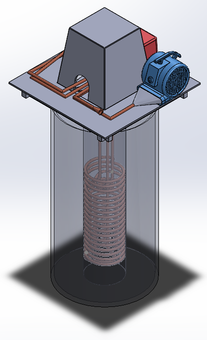
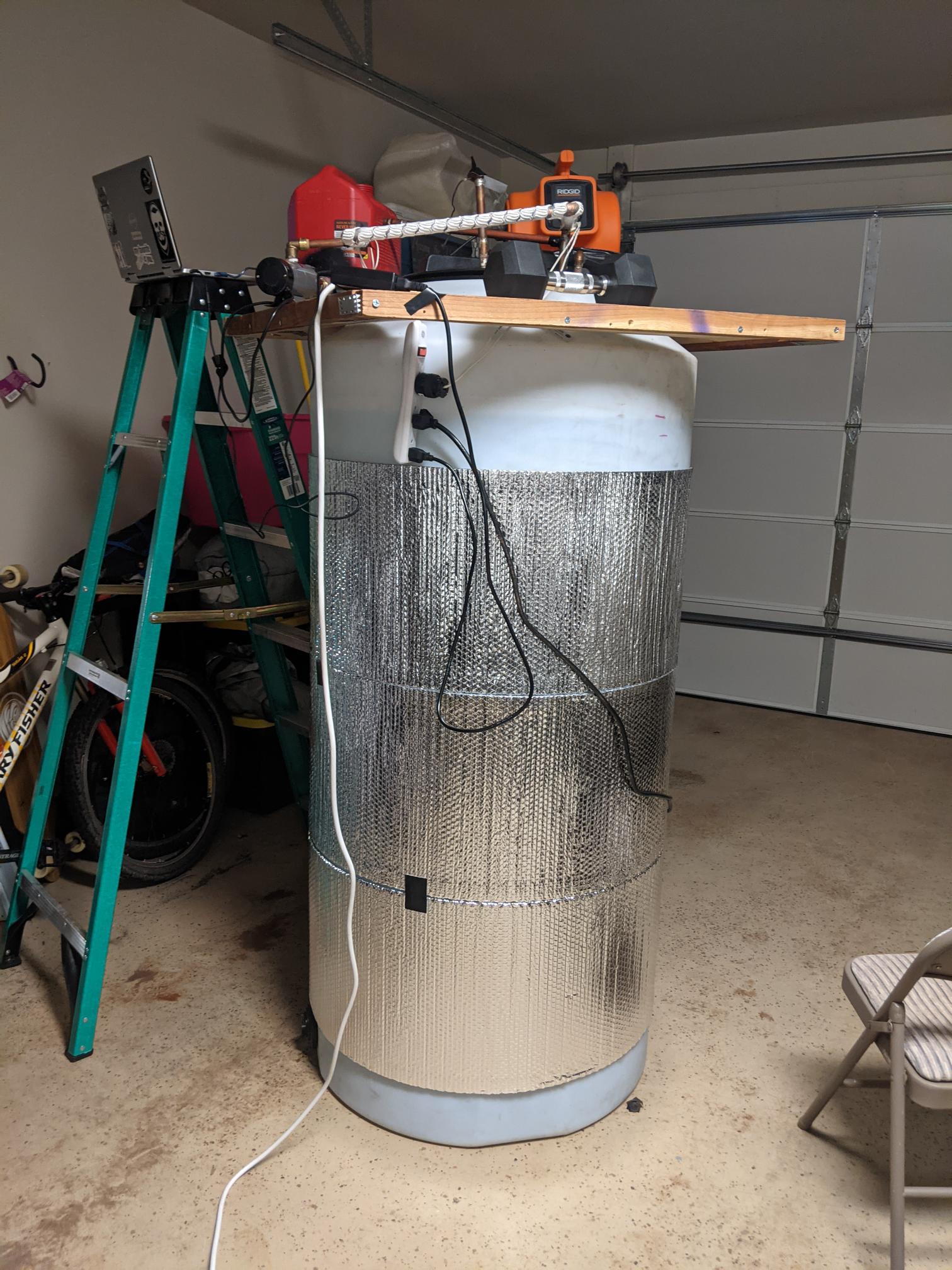
The image included below depicts the most current version of the prototype constructed by the Build Team. It shows the entire 220 gallon tank responsible for thermal storage, as well as the pipes and ducts used to transport fluid through the system and the pump and blower responsible for driving this flow.
Note that this image does not contain all of the components designed by the team; currently, it is missing the insulated cap or similar cap equivalent that will be used to insulate the pipes at the top. It does however show the insulation used for the tank, as well as the impementation of the heating tape and the location of the test rig used to evaluate the temperature parameters of the device.
This subsystem is responsible for moving the air through the storage device, where it is heated before being delivered through the system outlet. It uses a blower at the inlet of the pipe network to maintain airflow. It only operates at night, when the thermal storage device is discharging.
This subsystem is responsible for moving heat transfer fluid between the heat source and the interior of the tank. In this case, the heat source is heating tape wrapped around one of the pipes; however, future iterations of the design would use a solar thermal system to reduce the required electrical energy. A small, temperature-resilient pump is used to drive this flow. It only operates while the thermal storage device is charging.
This subsystem holds the thermal storage fluid, currently just plain, standard tap water. It heats up while the thermal storage device is charging during the day and cools down as the thermal storage device discharges and heats the house at night.
This subsystem is composed of three solar photovoltaic panels, controller, inverter, and battery. These are not currently represented in the CAD or physically integrated with the constructed prototype, but are intended to prove that the solar panel and battery are capable of powering the blower and associated control electronics throughout the night.
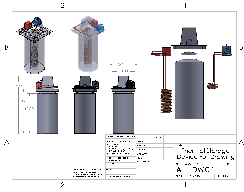
The image below contains a CAD drawing of the full system with the exception of the power subsystem. On the right side of the drawing, the charge and discharge networks are shown, demonstrating their relative size and position within the assembly. Note that all units shown are in inches.