Experimental Setup for Losses in Pipes and Fittings
Dr. Ciocanel is interested in upgrading some of the experiments associated with the Thermo-fluids laboratory and is supporting the development of a flow table that will allow the evaluation of major and minor losses during fluid flow through pipes and fittings. This flow table will replace the flow table experimental setup currently used in ME495, in order to improve the resolution of the data acquired during experiments and to allow performing of experiments over a wider Reynolds number range. Scope of Work: The scope of this project is to design, build, and evaluate a pipe flow table, equipped with at least two measurement systems for volumetric flowrate, to provide students taking the Thermo-fluids laboratory with a more robust and reliable experimental setup for evaluating major and minor losses in pipes and fittings. The experimental setup should be designed to also allow one to perform measurements that will allow the generation of the pump characteristic curve. Overall Requirements:
Develop a laboratory handout which should include a) theoretical introduction of the major and minor losses concepts along with the equations used to evaluate these losses based on measured pressure drops, and b) step-by-step experimental procedure for performing pressure loss and volumetric flowrate measurements.
The design team was able to meet all but one of the engineering requirements. The system features all required fittings and different pipe diameters (1-inch, 1/2-inch, and 2-inch) with a varaible flow rate using a vall valve. Additionally, all pressure measurements are collected using National Instruments LabVIEW software and data acquisition system that records the voltage difference across the pressure transducers. This voltage is convertly directly to pressure in units of PSI within the Virtual Instrument, which is then saved to a tab delimited file for further analysis.
The only requirement not met is the Reynolds Number Range desired. The original reange desired is 10000 - 1000000. The upper level with water as the working fluid is not achievable as it will require a flow rate of approximately 250 - 300 gallons per minute depending on the pipe dimameter. This placed a hard physical limitation on the system that would have required an extreme amount of pressure (approximately 3000 feet of head) which not possible within the design space. As such, the requirement is adjusted to simply be the highest possible Reynolds Number the design can achieve. The design is able to achieve a Reynolds number of approximatly 250000 which was found to be acceptable by the client.
Finally, the designs final test will be the longevity of the experiment. This is something that the team is not able to test as the 32 weeks of the program does not allow for it. As such, the ultimate out come of the design will be determined after years of use by the thermo-fluids lab within Northern Arizona University's Mechanical Engineering department.
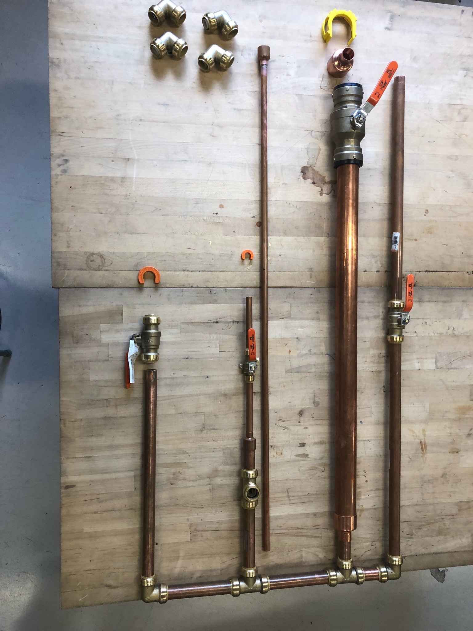
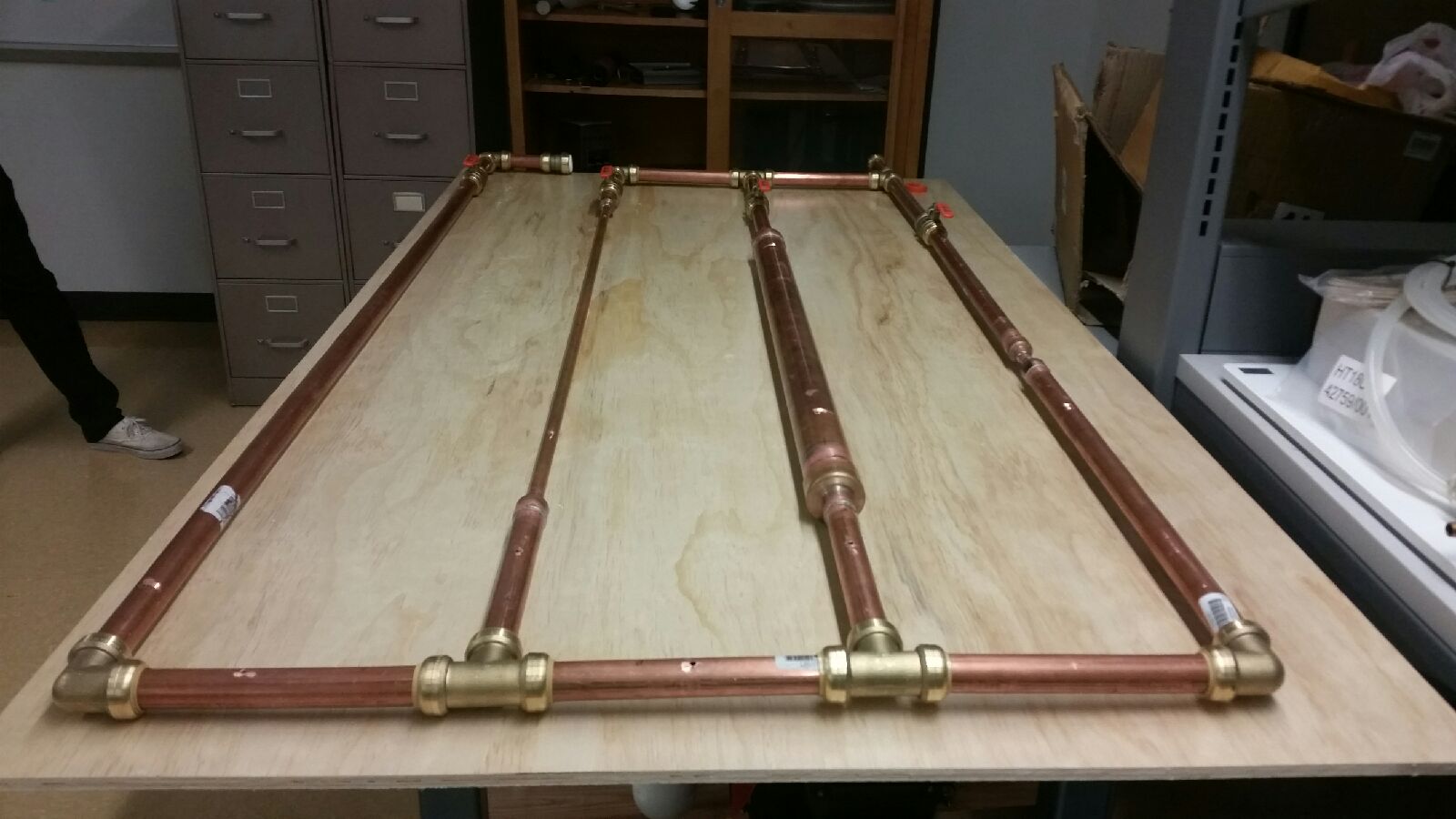
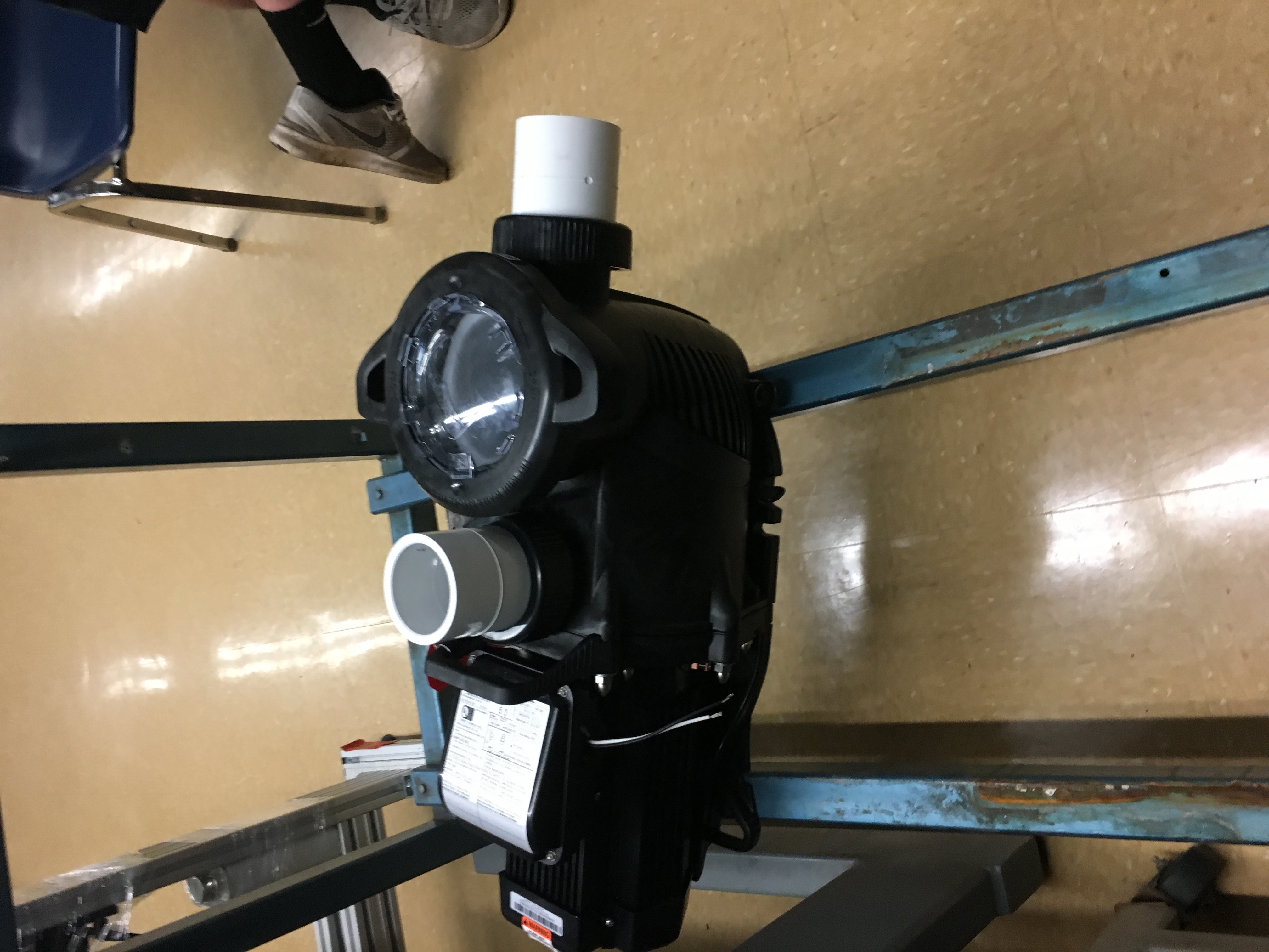
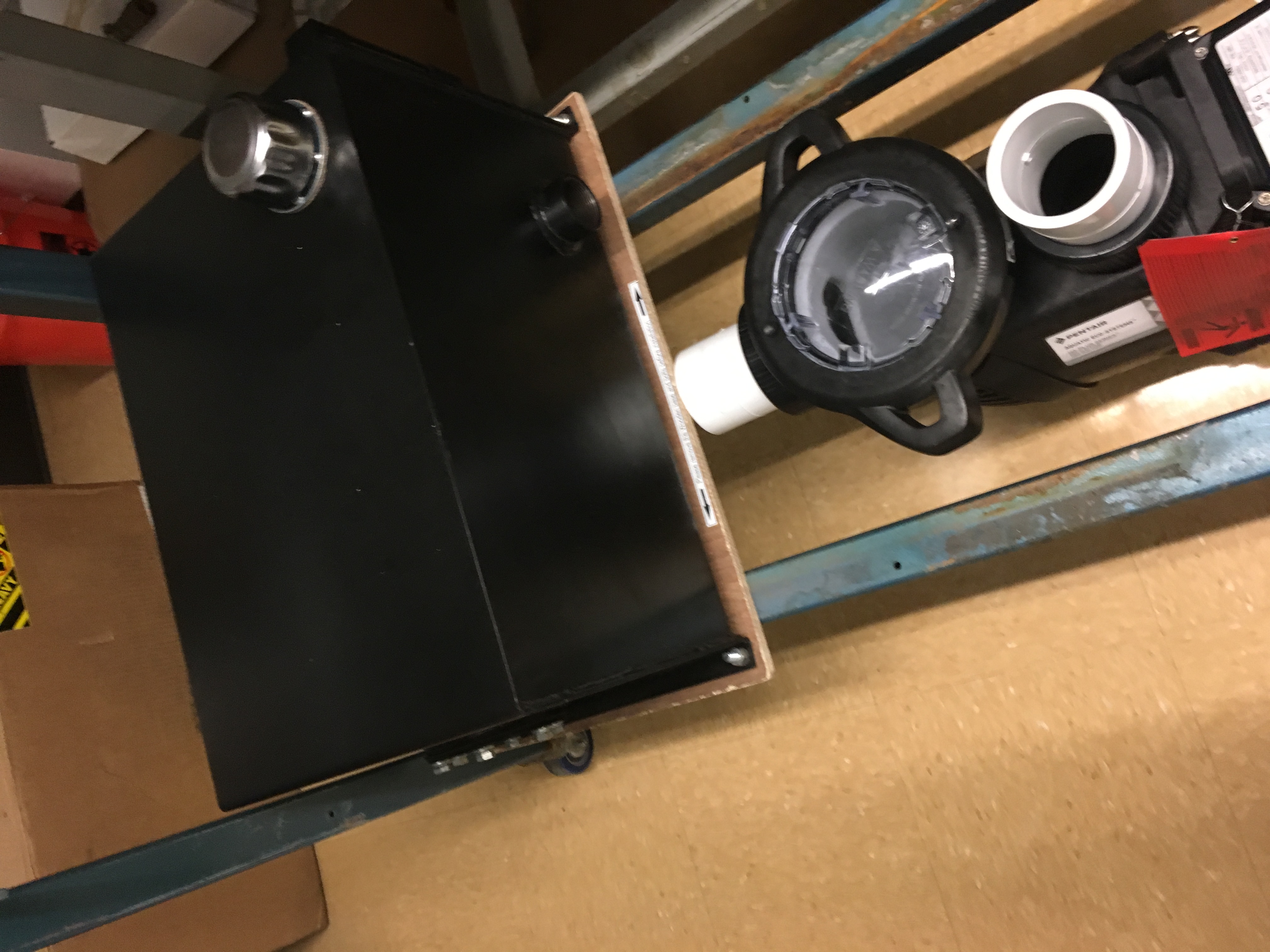
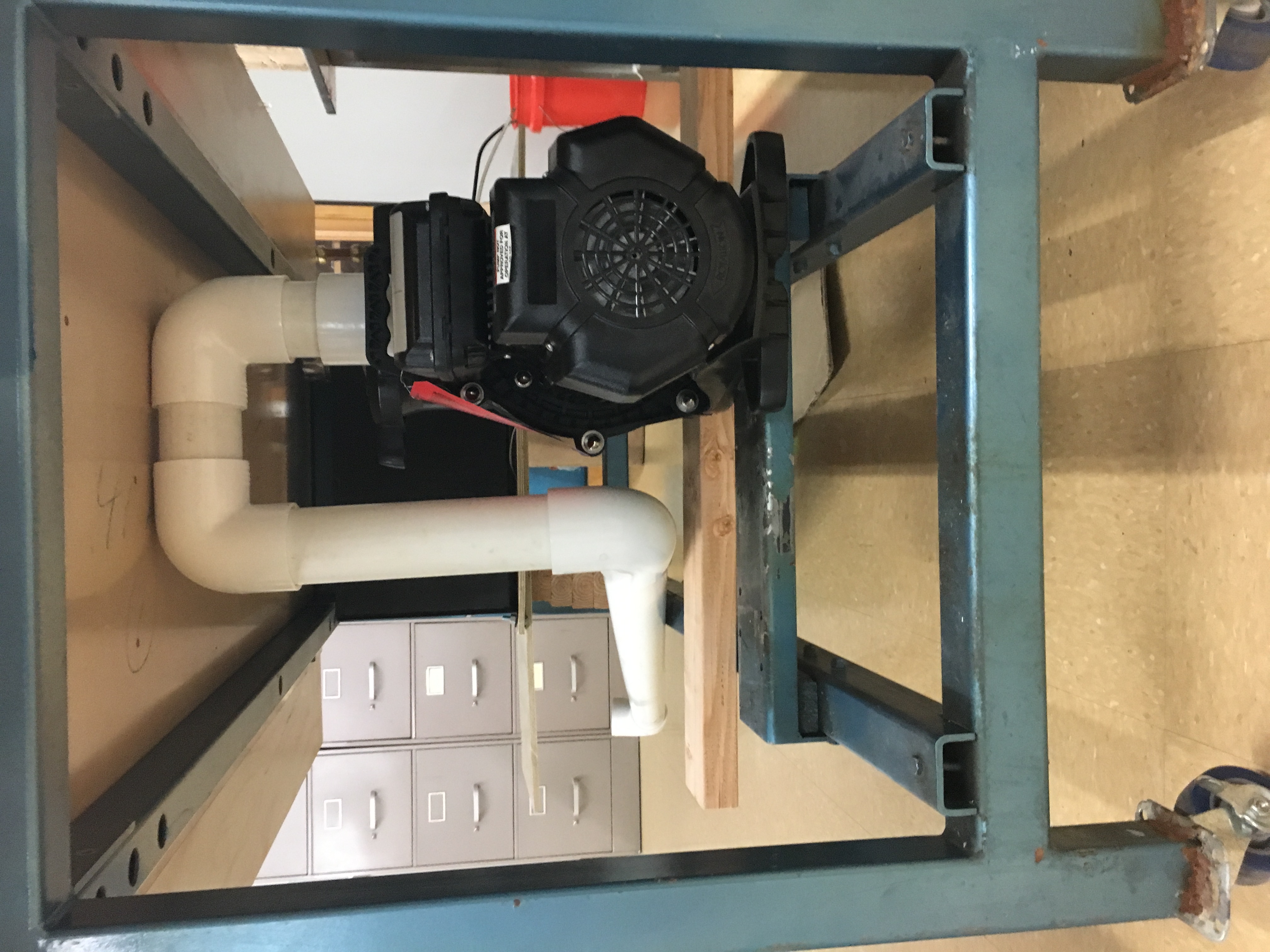
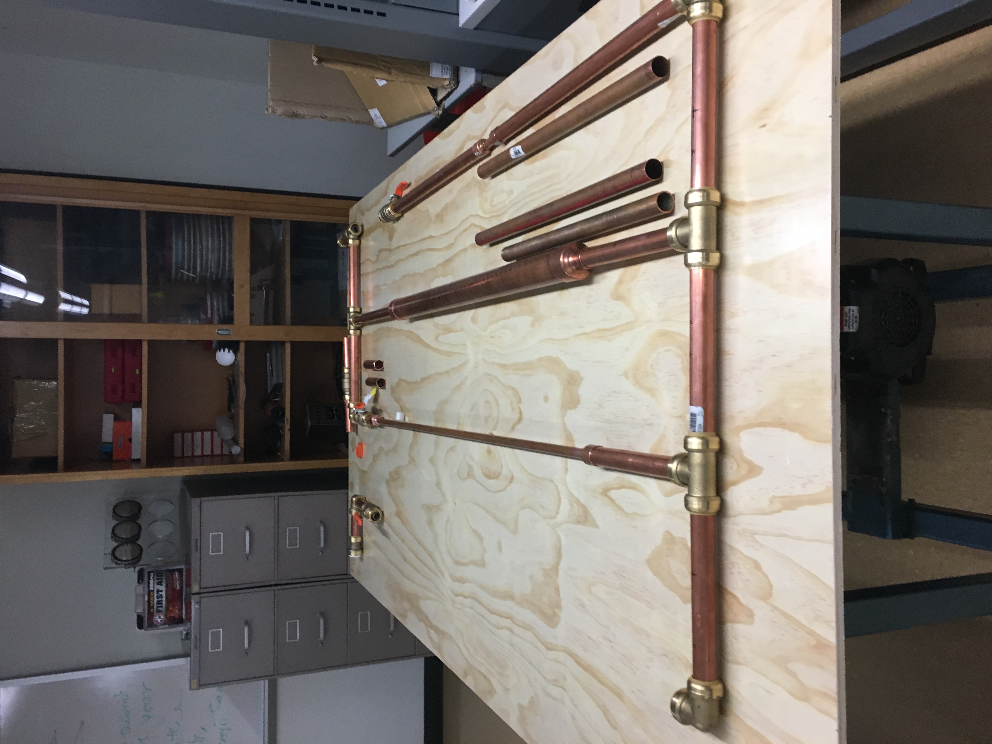
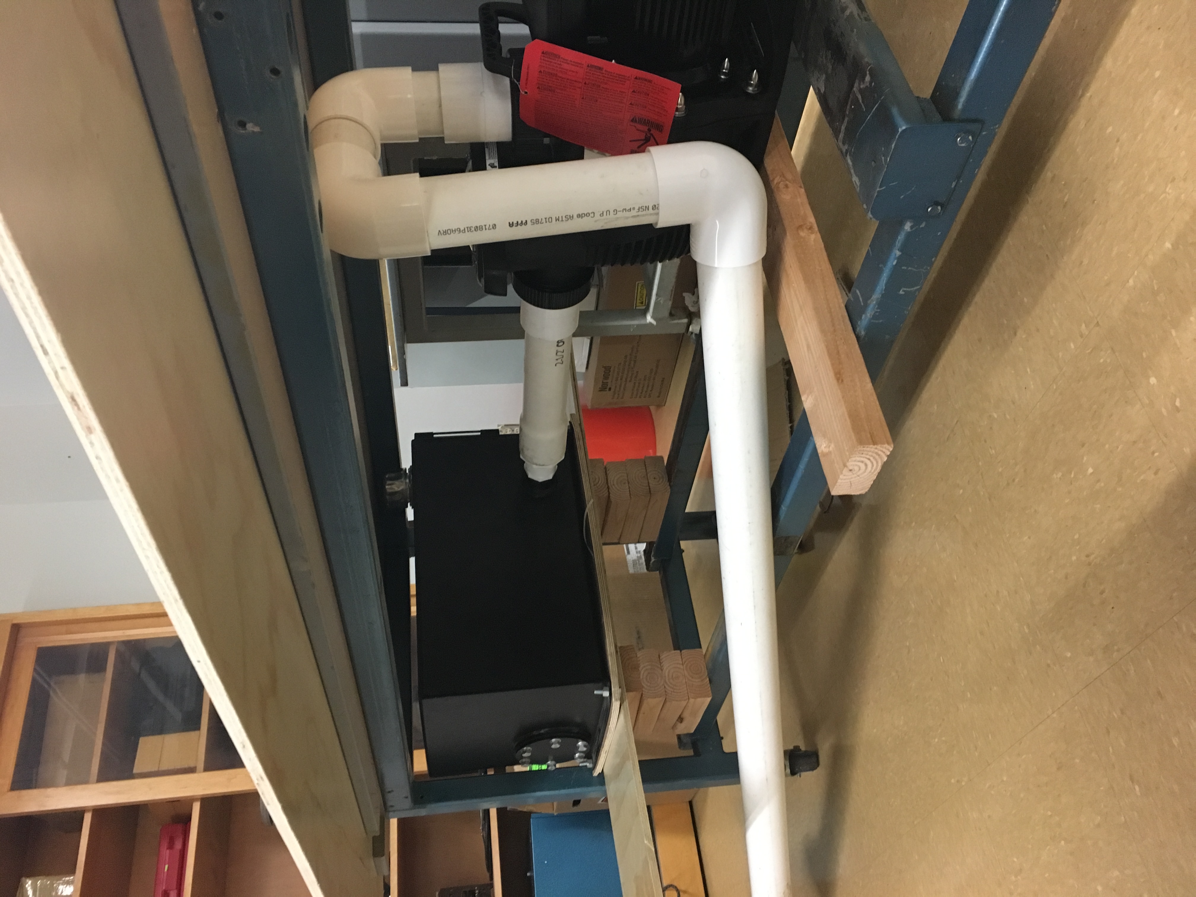
The construction of the epxirement is proceeding as planned. The pump and tank have arrived and a plan to mount and connect them is in place. The pump is the Pentair 5 Hp, Single Phase Pump and the tank is a 10 Gallon Hydraulic Reservoir. These two items will be placed along the bottom of the design and will connect to the upper section through the enterance and exit segements. Additionally, the team was able to salvage some of the original one inch copper piping and has bgain contruction of the upper section. Unfortunately, the remaining copper piping is currently in transit to the university. This delay is causing delays with the entire build process. Once the copper piping and fittings were deilvied the team was able to build the entire project. Additional delays were caused by the pressure sensors but the over all design was able to be constructed within a timely manner and tested for leaks. The lower section, made up of mostly PVC proved to be the most difficult section to work with. The team dedicated a large amount of time to attempting to seal all leaks but unfortunaely, when one leak was sealed, the water simply found another way to exit. As such, there remains two small leaks within the PVC section that the team was unable to rectify. Once the pressure sensors were delivered, the team was to mount them to the system using brass threaded taps and plumpers tape. Connecting the sensors to the data aquisition device proved to be difficult as it required grounding both the DAQ and the sensors to the same ground which was not apparent in the directions. Once the sensors were tapped and connected to the DAQ the team was able to validate the engineering requirements.
Shark Bite connectors are compression pased, teeth locking pipe fitting connector for PEX and Copper piping. They utilized a series of metal teeth to lock the pipe into the connector, while an inner collar provides a method for reducing the head loss over the fitting. These connectors have a maxium pressure of 137 kPa (200 psi) which is well within the maximun pressure the system will experience.
These connectors will be utilized where ever possible to decrease build time and complexcity, while increasing the ability to maintain, repair and upgrade/update the system. These devices are more expensive than normal fittings but the benefits to the system greatly out weight the additional cost.
This design was selected because it meets the requirements of the client as well as the engineering requirements. The exact diamters of the design are still to be determined. The specifictions of the design are:
The design also fits within the current space reserved for the pipe fitting table with the Thermo-Fluid lab.
From the decision matrix for selected materials, the two top materials are Copper and Plastic piping. Both are currently being considered as they both have different strengths and weaknesses. Plastic, for the cost saving and ease of use, and Copper for the durability and flexibilty of applying pressure taps.
There are five main areas of concept generation that the team identified as important to developing a succesfull concept. The criteria for selection is based on the project description provided by the client and the engineering requirements developed using the house of quality. The engineering requitements are:
Variable flow rate pumps
The team used a gallery method to create ideas for the over all pipe system layout, and example of which is located to the left. All examples can be downlaoded here.
The team conducted a House of Qaulity analysis of the engineering and customer requirements to determine what the most important aspects of the design space are. From this analysis, the team determined the following:
House of quality as of 2/16/2018