Progress in Design:
The design was well executed and the progress can be seen below.
Tools used to complete the build included:
Hacksaw, drill press, belt sander, tig welder, metal files, level, tape measure, hex keys, lathe, and a grinder.
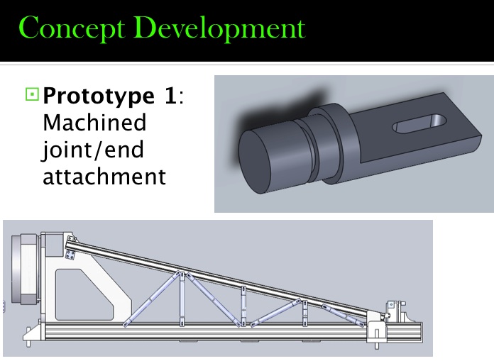
Prototype 1:
Restrictions-Weight and time to develop.
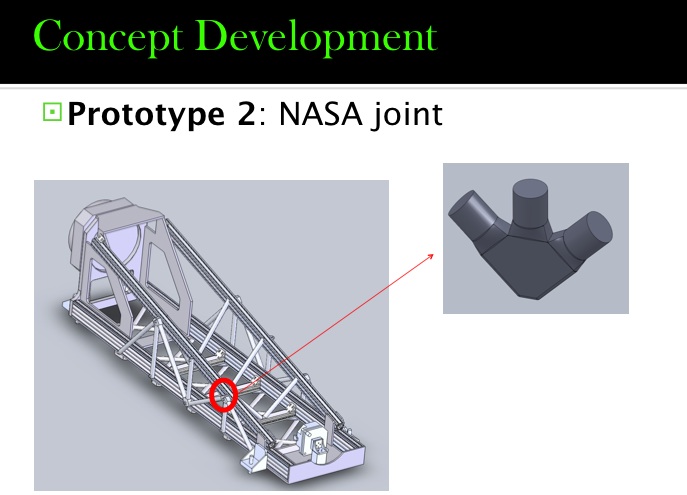
Prototype 2:
Restrictions-Weight and time to develop.
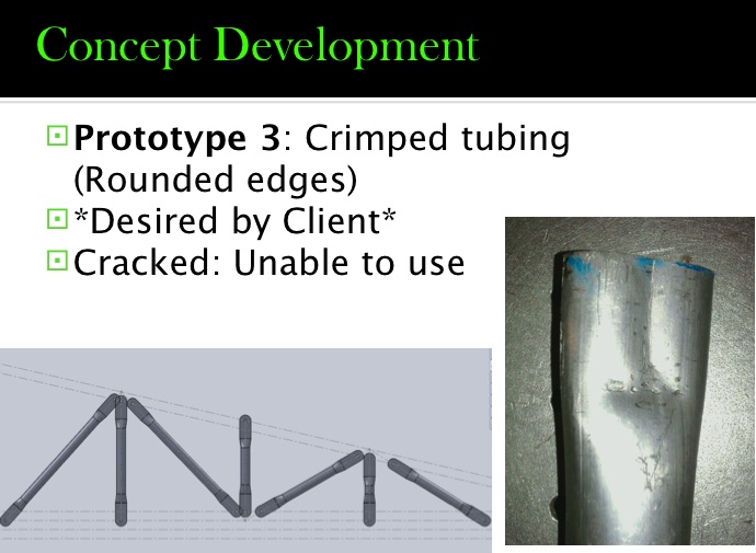
Prototype 3:
Restrictions-Tube did not allow for metal on metal contact and cracked.
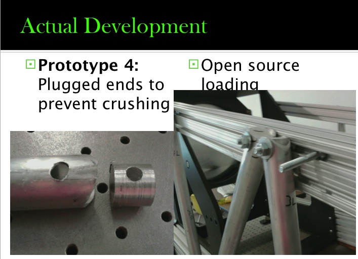
Prototype 4/Actual development:
Light weight and we were able to get metal on metal contact along with open source loading allowing for tube/members to be tightened against the rail for max stiffness.
Problems:
Problems encountered during the build included the Aluminum tubing not being able to crimp as desired.
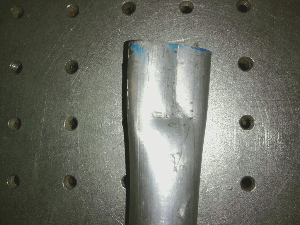
This made our client uneasy about securing thin walled tubing to the side of the beam compressor without a metal on metal contact. So we altered our design by turning down an aluminum shaft and cutting it into small plugs to be placed in the end of our tubes and simulate a metal on metal contact.
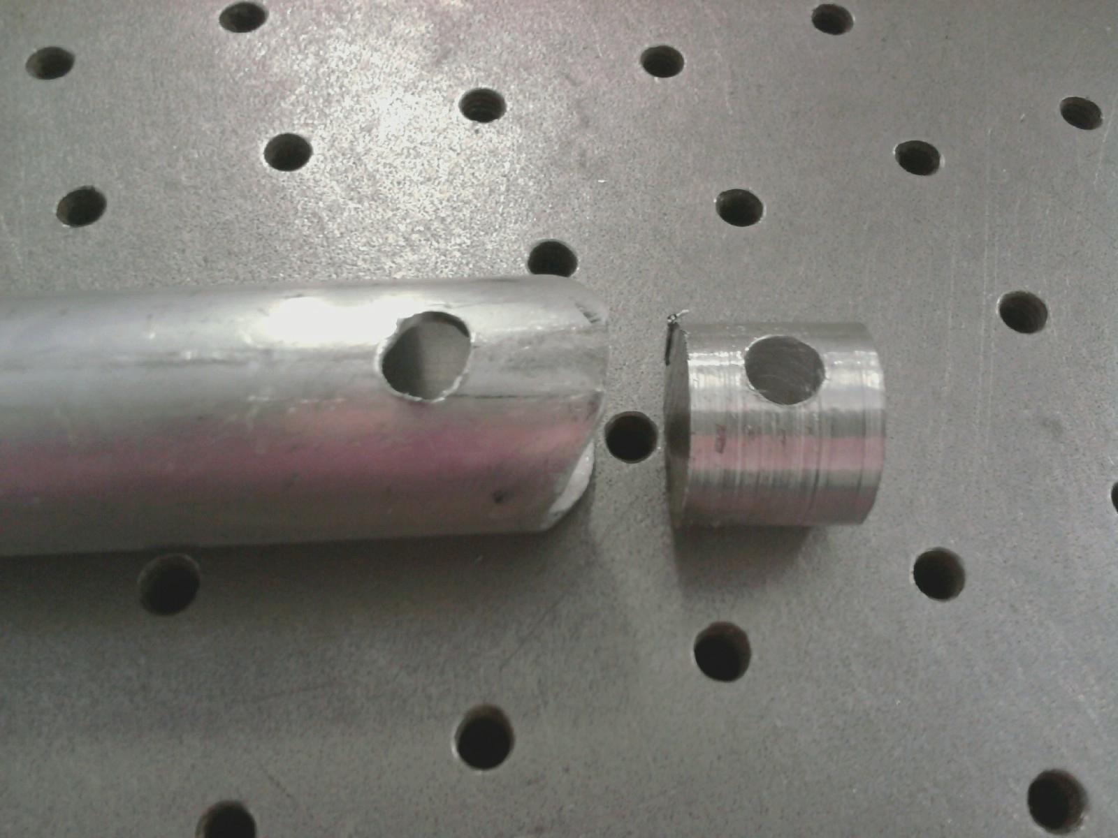
This made our client much happier and allowed us to really tighten all open source bolts to allow for max stiffness on the beam compressor.
Milestones are described below as stages.
First stage: Remove all existing support members.
Second stage: Build all members and attach to the beam compressor.
This is a side view of the beam compressor fully assembled.
This view is looking from the top of the large mirror down the length of the beam compressor.
Third stage: Testing with Labview

Labview running as testing is underway.

Labview block diagram.
Fourth stage: Analyze all data collected from Labview.

Numbers collected in excel.
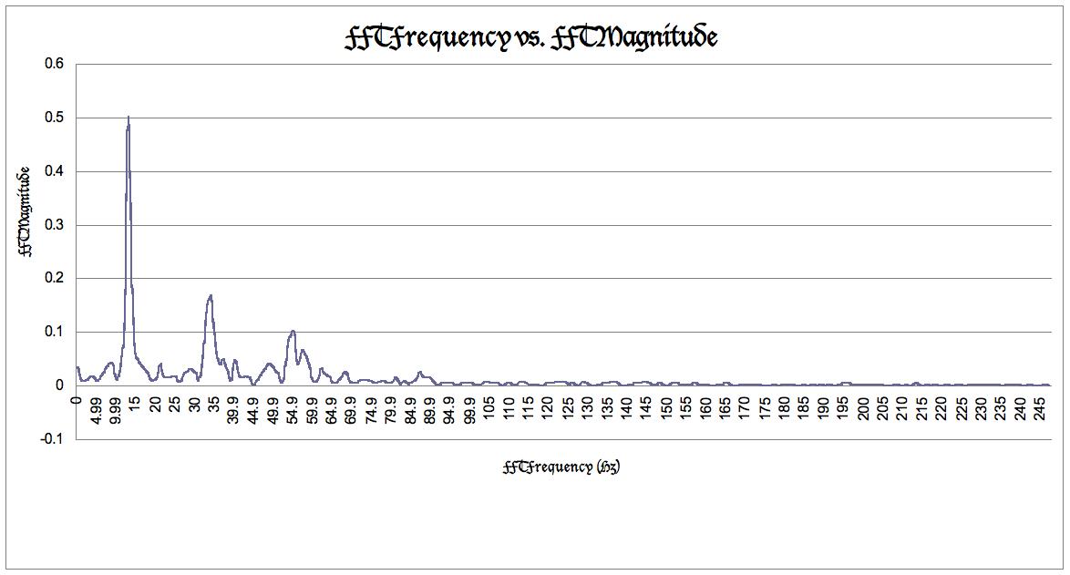
First case testing graph produced in excel.
For more test results please refer to the testing page and final page.