So, the umbrella concept has a fatal flaw: mainly that it doesnt generate a large enough friction force against the wall of the crack.
How then do SLCDs generated
the sufficient force? ![]()
Well... here we get a little technical
![]()
|
The constant angle cam is the current market standard in active friction anchors for rock climbing. This design utilizes a logarithmic spiral to keep the angle at which the reaction force from the wall is applied constant. The logarithmic shape maintains a constant normal force (at a constant load) regardless of the span of the crack. The camming angle is the angle at which the force is applied and is defined as the angle made between the radius of the spiral and the line tangent to the spiral at the intersection point (figure on the right). The camming angle determines the range and holding power of the cam. A larger camming angle increases the range, but decreases the holding power. Current cam designs use an optimized camming angle of approximately 14.5 degrees. Because the angle at which the force is transmitted is constant, so are the forces. The maximum force in the cam lobe can be calculated as follows:
|
logarithmic cam shape and force transmission
our original design concept for optimizing the current SLCD design
|
This gives a maximum force in the lobe of 51.9 kN. Given the strength of 6061 T-6 Aluminum (240Mpa) the minimum cross sectional area for the cam lobe can be calculated as: 2.2 cm2. Currently high strength alloy axles are used to link Wired Bliss cam lobes. We planned on using the existing axles in our design. However, we ran into problems with these axles. Find out why on the testing page.
In our current design, logarithmic curves such as the one shown above are utilized. This keeps the camming angle constant at 14.5 degrees from horizontal regardless of the rotation angle. Because of this a constant force is transmitted to the wall and the necessary friction force is developed to withstand a 13kN load. The constant camming angle should eliminate our problems with our range. By only using a section of a logarithmic curve we planned reduce the weight of a standard cam while maintaining a large range.
As we had spent most of our time concentrating on the umbrella design, we decided that inorder to develop a workable prototype for Wired Bliss that met all the designated requirements, we would concentrate on optimizing the design of the cam lobes on our SLCD and use standard parts form Wired Bliss for the trigger, axle, wires, etc. This would to simplify our design and make it easily integrateable into the Wired Bliss production cycle.
Our chief goal at this point was to design the lightest cam lobes possible and still have a safe, functioning cam that allows for an effective range for the device.
|
modified cam shape
|
On the left, you see the shape of the new cam lobe that we have designed. This cam still implements the logrithmic of its contemporaries, howver, note the large removed sections from the center of the cam. This was done to reduce the weight of the cam as much as possible. In order to determine if there was still enough supporting material left in the cam to withstand the loads generated by a fall, we constructed a Finite Element model using COSMOS finite element analysis (FEA) software. Click on the full assembly image on the left to see a 3-D video clip (1.9M).
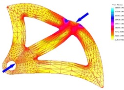
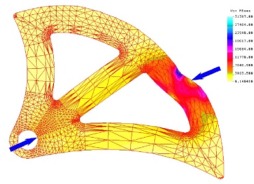
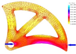
Once again on the left, you see a series of deformation (magnified) and stress plots produced by our finite element analysis, simulating a series of six loading conditions that could be achieved during the normal use of an SLCD with using these cam lobes. The factor of safety (FS) is determined by dividing the maximum present von Mises stress by the yield strength of the material being loaded, in our case 6061 T651 aluminum. As you can see, the analysis predicted a minimum FS of 1.12, which, because the 13kN load requirement already has an implied factor of safety, falls well within our guidelines. The maximum factor of saftey occurs when the SLCD is in its most open position, causing the cam to be loaded across its largest supporting member at the bottom. As you can see, there is relatively little deformation compared to the other load cases and consequently the factor of safety is also much higher at FS = 3.96. As it turns out, this model is not completely accurate, as we will see in the testing page. The problem lies in the 2-dimensional assumtion of the model. As it turns out, while the cam lobes themselves could me modeled as 2-dimensional, the forces and moments actually acting on the lobes though the axle have a 3-dimensional aspect to them. This causes the cams to twist in the area near the axle, resulting in a plate bearing failure at the axle hole. See the testing page for further details. |
|
Finite Element Analysis of the new cam lobes: |
|
|
|
|
|
FS = 1.6
|
|
|
|
|
|
FS = 1.14
|
|
 |
|
|
FS = 1.13
|
|
 |
|
|
FS = 1.12
|
|
 |
|
|
FS = 3.96
|
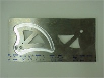
As stated above, for our protoype, with the exception of the cam lobes themselves, all components of the prototypes produced were provided by Wired Bliss LLC. However it was necessary for us to produce the actual cam lobes ourselves at the CET (College of Engineering Technology).
This was done using the
ProLight CNC mills in the CET. All the G-code for these machines was input
by hand by members of GM^3, as an initial set of G-code commands that were
generated by Bob-CAD from our technical drawings proved to not function correctly
on the ProLights ![]() ...
...
The cams were machined from 0.25 inch 6061 T651 aluminum stock. The inner cuts were cut using a 1/8 end mill cutter and the outer cuts were cut using a 3/8 end mill cutter.
 |
Click here to see a video of the tool path (416k). |

