Navigation
SpecificationsRegulations
Process
Mechanical
Avionics
Telemetry
Final Report
Specifications
From the beginning, this project has been meant to span multiple years. The requirements and specifications for the project below are not limited to just the first year.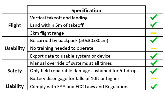
The specifications with a green check mark were completed to satisfaction but all work done is capable of improvement. Those with a yellow dash were not completed, discovered to be impossible/impractical, and/or were not fully tested.
The three kilometer flight range found to be unnecessary and was never tested. This requirement conflicts with the FAA regulation of keeping flight within visual range, and was thus foregone for the time being.
Although no training is necessary in theory, in the unlikely event that a user must take manual control of the drone (as FAA regulations dictate must be possible), the user must be able to fly the drone with a traditional RC controller. As a result, some level of training is required, though the system's use is still quite comprehensible fo non-engineers.
No drone as of 2015 contains a battery disengagement feature and therefore no information is available on such a system. This feature proved to be too large a task to be completed in the first year and could be a senior design project in its own right. In addition, the largest safety concern for the battery is the event of a puncture, and the current system safeguards against this possibility with electronics housing.
Regulations
The Federal Aviation Administration has jurisdiction over flight paths of unmanned aerial vehicles under certain conditions. The conditions are set to allow for unregulated flight under reasonable circumstances, largely meant for hobbyists. The FAA's current regulations are as follows:|
Fly below 400 feet
Remain clear of manned aircraft Not fly near people or stadiums Avoid carelessness or recklessness while flying |
Keep within visual range
Not fly within five miles or airports Aircraft cannot weigh more than 55 pounds Allows for manual control at all times |
The FAA is set to hold additional regulation meetings in September 2015 where these conditions are expected to change.
Process
The process by which the drone completes a tracking flight is shown below.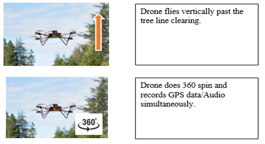
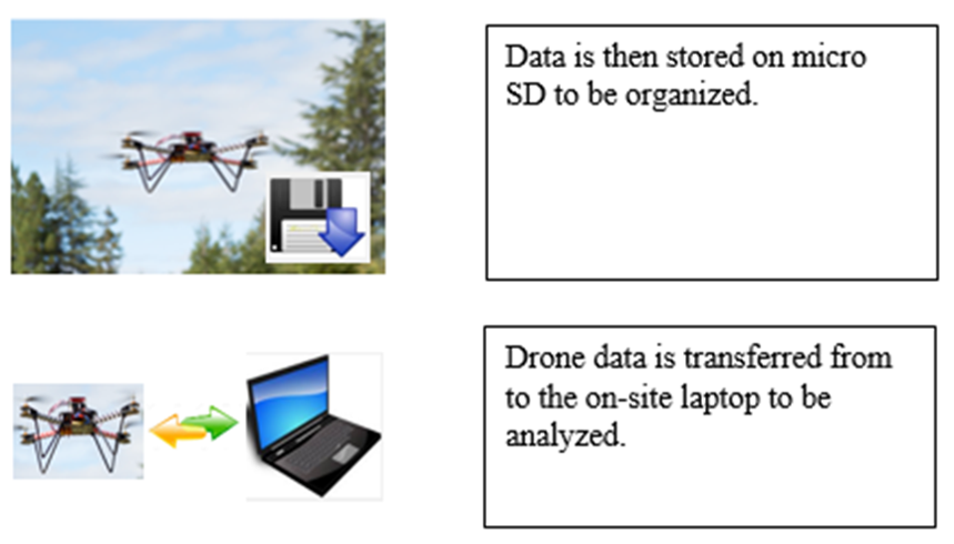
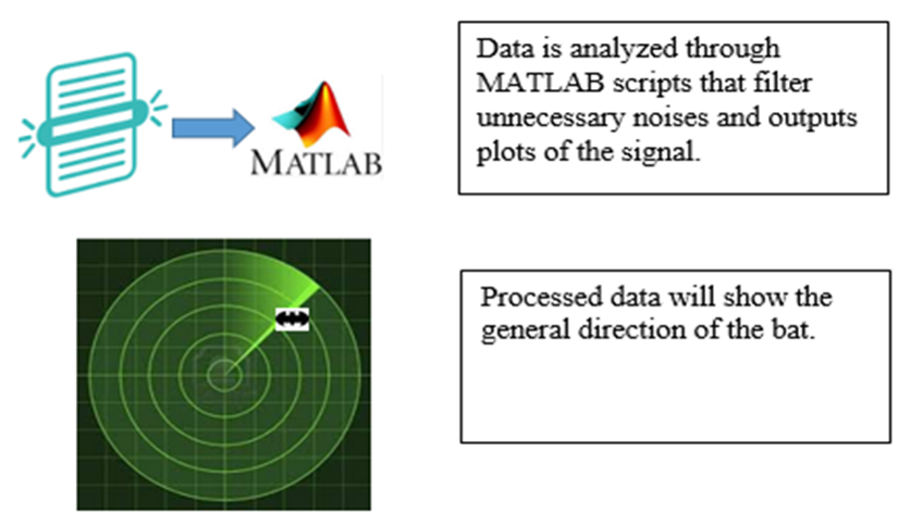
In order to create a drone that could accomplish this, three teams were created, dedicated to different aspects of its design.
Mechanical
The mechanical subteam performed all design, fabrication, and analysis of mechanical components including, but not limited to, the frame, landing gear, and housing.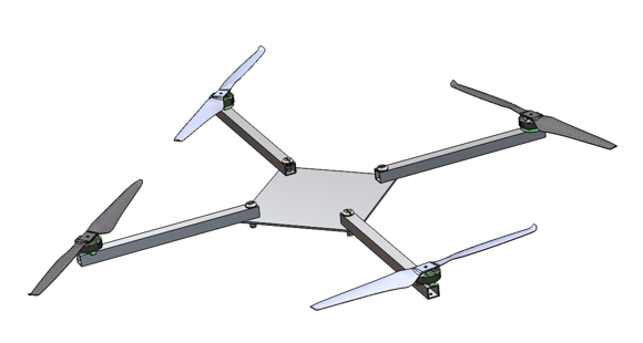
An initial prototype frame was produced for use during testing and development. This frame, although light in weight, was crude and did not fulfill the requirements of this project. It was, however, capable of flight and showed itself to be invaluable for testing before the final frame was ready.
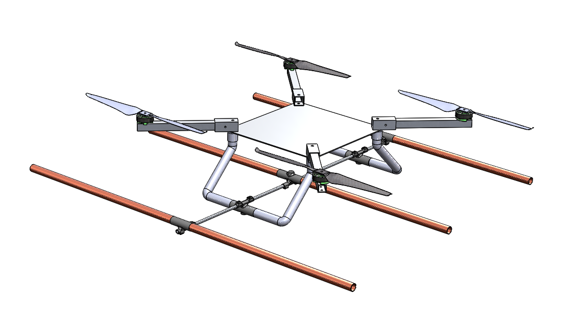
The final frame design features landing gear, an increased surface area on which to place the elecronic components, a system to attach the antenna, and detatchable arms.
As the above images show, the design was done digitally and a few of its components were fabricated with the use of a 3D printer.
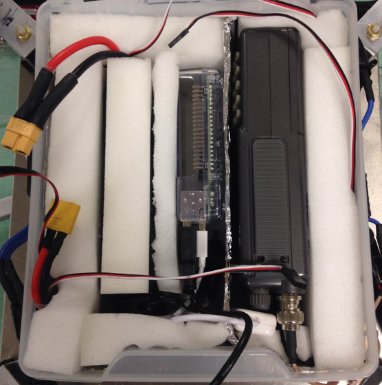
Electronic components used by the avionics and telemetry subteams were placed in a secure housing, padded, and shielded, preventing them from affecting other components with the electromagnetic interference they produce or, conversely, from being affected by existing fields outside the housing. The housing also provides some degree of physical protection to these components in the event of a crash.
The mechanical subteam also attempted to create a "battery breakaway" which, under emergency conditions, would disconnect the battery from the remainder of the system. Several possible designs were discussed, which are outlined in the report, but all pose significant challenges that must be overcome before they will yield working systems.
Avionics
The Avionics subteam had the task of making the drone fly as its main purpose but also had a secondary purpose of developing, maintaining, and unifying the software used on the drone.The team created four main systems/components in order to create flight: the drivetrain, radio control, control system, and ground station.
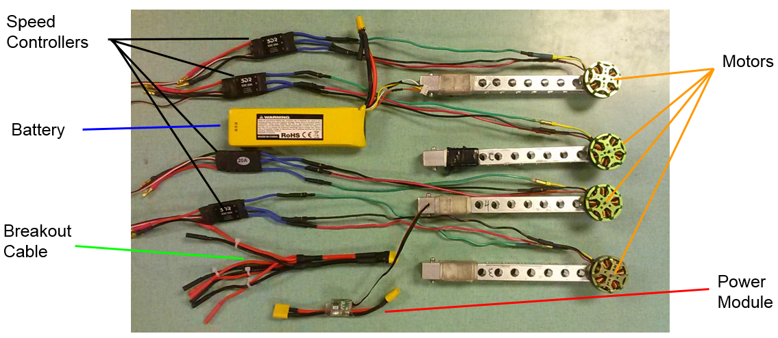
The drivetrain consists of a battery, four electronic speed controllers, four motors, a breakout cable, and a power module. The breakout cable delivers electricity to all four motors and the power module serves the purposes of powering the flight controller (see below) as well as determining the remaining battery percentage.
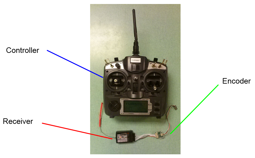
The RC controller is not intended to be used during tracking flights, but must be available for emergency situations. As such, the user(s) must be capable of using the controller to fly the drone. We do not expect any such users to complain about this necessity. It's quite fun.
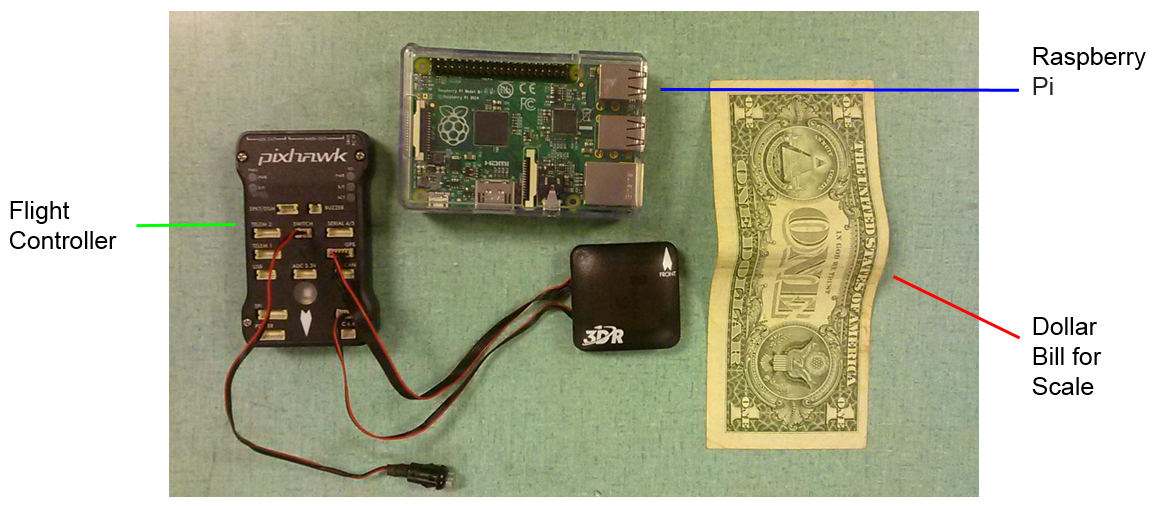
All "thinking" done on the drone is performed by the two electronic devices seen above. The square device is a GPS module and feeds its data to the Pixhawk. The Pixhawk is a readily-available flight controller which uses mathematical models to maitain flight at specific heights, speeds, angles, and so on. The Raspberry Pi is a popular single-board computer amongst hobbyists but also made for an excellent "brain" for this project. It handles communication with the ground station (see below), communication with the Pixhawk, flight path determination, sensor measurement recording, and more.

Although it can take any form, the ground station is currently in the form of a Android application that launches and lands the drone, with the additional feature of displaying a map with the users' location and the estimated location of the desired bat (once completed).
Demonstrations of the drone in flight, among other demonstrations, can be seen on the Videos page.
Telemetry
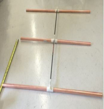
The telemetry subteam was responsible for all work pertaining to receiving a signal on the drone. This included designing an antenna, selecting a receiver, and creating algorithms in MATLAB to filter and display data.A three-element Yagi-Uda antenna was chosen for its balance between precision and weight. The telemetry team collaborated with the mechanical team to create the final antenna, shown below, which is functional, durable, collapsible, and relatively lightweight.
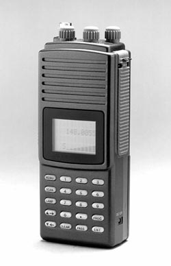
The receiver used is an R-1000 telemetry receiver, chosen familiarity and availability for our clients.
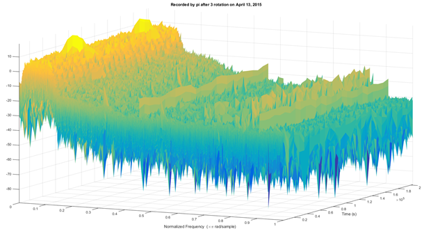
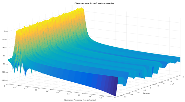
A major challenge in using software to pick out the strongest signal over the course of a tracking flight is noise. Below is an example of audio data before and after the use a Butterworth filter implemented in MATLAB, which filters out noise at all frequencies besides the desired frequency.
As an end goal, the process will not make use of MATLAB and will rely solely on the software, even if it must be developed, on the ground station and Raspberry Pi.