Project Description
Description
To accomplish this project, our group is planning on creating wireless modules to read sensor measurements and feed that data to an accessible server and webpage. The client has asked our team to create sensors that can read the temperature, humidity, and light levels inside the greenhouses. This data must be accessible remotely and should be updated at a regular pace. Our client has given us various requirements and constraints that we must follow to accomplish this project. Listed below are these requirements.
Requirements
1. Humidity Sensor:
- 1.1 Low hysteresis, ideally accurate for up to 5 years.
- 1.2 The sensor needs to be accurate, within +-2.5%.
- 1.3 Low power usage when measuring, 1-10 microamps
2. Temperature Sensor:
- 2.1 Operable at temperatures between 40 and 90 degrees fahrenheit.
- 2.2 An accuracy of +-1.5 degrees fahrenheit.
- 2.3 Low power usage, when operating it should be between 10-100 microamps.
3. Light Sensor:
- 3.1 The light sensor will measure illuminance in lux.
- 3.2 Low power usage, when reading light usage should be in the range of 100-200 microamps
4. System:
- 4.1 The system will need to be water resistant to withstand moisture and mist (IP56 rating, Ingress Protection).
- 4.2 The sensors will need to be able to be picked up and moved to different locations.
- 4.2.1 Able to move individual units to measure different pods in the greenhouses.
- 4.3 The system will have remote access to data.
- 4.3.1 Able to access temperature, humidity, and light readings from the website.
- 4.4 Withstand temperature between 40 degrees and 90 degrees fahrenheit.
- 4.5 Notification to the user if temperature is outside designated safe range, depending on each greenhouse the ranges are 70-85 degrees fahrenheit.
- 4.6 The system should operate with minimal user interaction.
- 4.7 Each unit must be self sustaining and not require outside power.
- 4.7.1 Unit must be able to charge and power itself to reduce down-time and interaction with the unit.
5. Data Collection:
- 5.1 Data will be categorized by each greenhouse.
- 5.2 A daily report must be able to be given with a readout of all readings for that day and stored in a text file to be sent to the client.
- 5.2.1 Data readings will be stored in a database (SQL database)
- 5.3 Must collect data at least every hour.
- 5.3.1 Data collection will ideally happen every 5-15 minutes.
- 5.4 Must be capable of sending the data to a website for mobile use
- 5.4.1 The website should be able to view sensor data from all modules within the 8 greenhouses.
Architecture Description
Our modules are split into 3 major parts of input, output, and power. The power circuit consists of a solar panel conected to a regulated charge circuit that is directly wired to a 18650 Lithium Battery. From the charge circuit we have a booster to boost the voltage from the regulator circuit to have the proper power for the ESP modules. The Output will be over a local wireless connection to our raspberry pi server which will handle the packets of information and save them to a log based on time accessed. After that the Pi server will handle portions of the data and update the website with a portion of the Log. The Sensor Data of the module will be recieved and sent to the esp using the BME280 and BH1750 sensor modules. Once recieved the Esp will make a packet of the data to be sent to the server.
Project Sponsor
NAU Research Greenhouse
Our team's project sponsor is Adair Patterson, who is the manager of the Northern Arizona University Research Greenhouses.The reserach greenhouse at NAU has supported projects that have encompassed many disciplines and departments. During the past decade the research greenhouse has expanded their mission to include growing plants for habitat restoration, devoloping a campus aboretum, partnering with local communities to build public gardens, and plant native landscaping with NAU Facility Services.
Past projects of the NAU research greenhouse has included research on reestablishing native species after wildfire, threatened alpine plants, riparian restoration, and more. Research on ponderosa pines and climate change, mine remediation, and Colorado River flooding.
Link to the NAU Research Greenhouse Website
Project Design
System Architecture
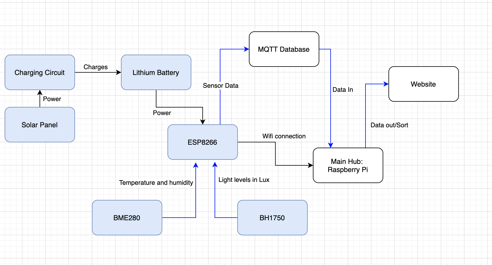
Below is the schematic of our System Architecture. This system architecture gives an overview of how our solution will function. The power system, seen in blue with black arrows, is the system that includes our solar cell, charge circuit, and lithium-ion battery. The power system will provide power to the ESP8266 and will be fully self-sustaining with no user interaction needed.

System Architecture Schematic
Below the ESP8266 module, we have our two sensors feeding light levels and weather data into the ESP8266. These two sensors are the BME280 and BH1750. The BME280 provides temperature, humidity, and pressure data. The BH1750 provides light levels measured in lux.
Lastly the white portion of the system architecture is the connection to a Raspberry Pi and MQTT server. The MQTT server will provide data-in for the Raspberry Pi, fetching the sensor data over Wi-Fi connection. The data will then be stored on the Raspberry Pi and published to this website as needed.
Hardware and Software
For this project, our team will be using the ESP8266 microcontroller in tandem with the BME280 and BH1750 sensors. The BME280 is a sensor that offers data readings for temperature, humidity, and pressure. The BH1750 offers light level readings in lux or lumens per square meter. Both of these sensors utilize the i2C communication protocol, offering quick and easy setup of the sensors.

ESP8266 microcontroller with BME280 and BH1750
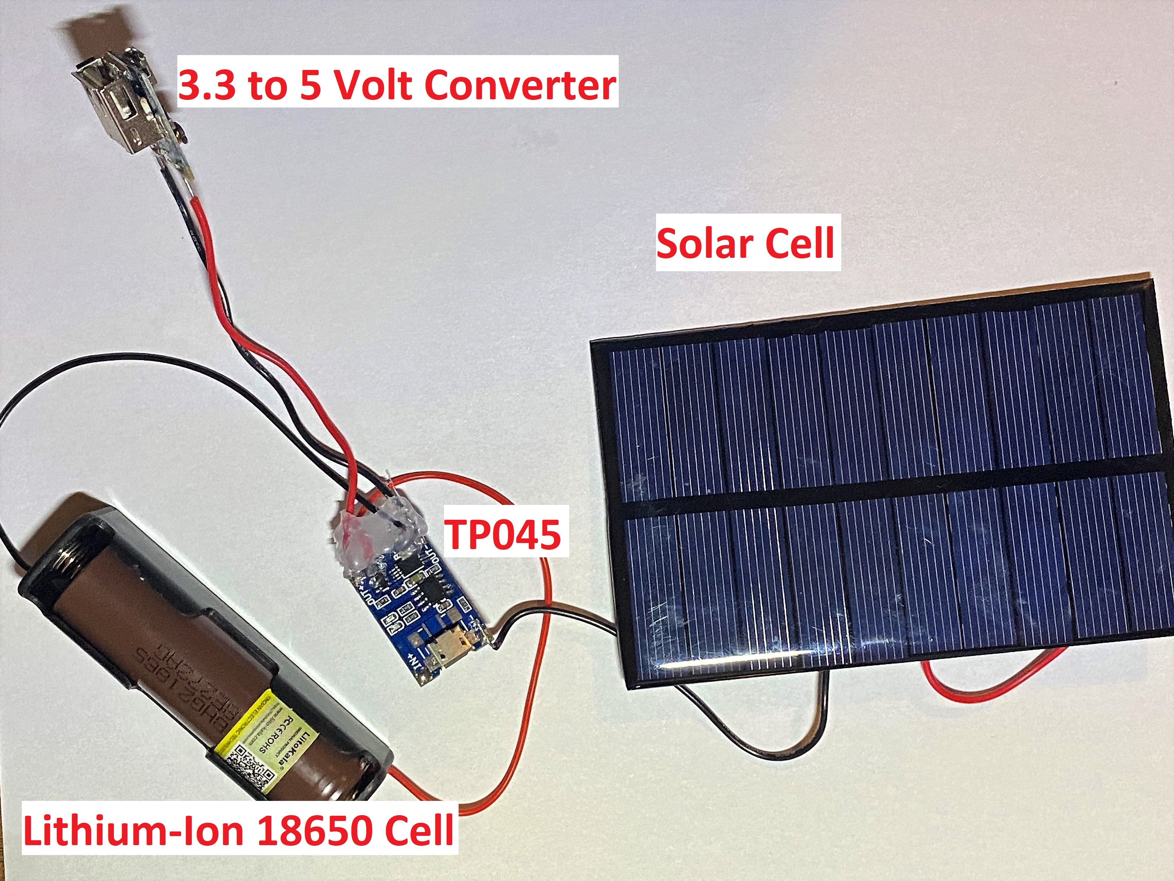
The goal of this project is to create a minimal interaction between client and module. For this reason, our team is using a lithium-ion 18650 cell with a solar cell to recharge. A TP045 charge protection circuit is used to prevent overcharge, overdischarge, and short circuiting across the battery. Lastly a highly efficient boost module is used to convert the 3.3 to 4.2 volts from the 18650 cell to the 5 volts needed to run the ESP8266.

Charging Circuit
Our team will be utilizing Python and the Arduino IDE to run code on the ESP8266 microcontroller and a Raspberry Pi 3. The Raspberry Pi will be using a combination of Python and a Mosquitto (MQTT) database. This will allow for transfer of data between the ESP8266 and Raspberry Pi similar to HTTP post requests. Below are a few snippets from the Arduino IDE of pulling sensor data from the BME280 and BH1750.
Data Read Code Snippet