Hobby Scale Dynamometer
Phase Three: Detailed Design Phase
Design Concept
Figure 1 contains a low-level overview of the proposed system.
The design of the dynamometer has been pragmatic in nature. The team strove to find the most direct means of obtaining the desired information about the motor. The fundamental material decisions to be made for the project design were found in the following domains: choice of drive motor, control systems, embedded systems, power delivery and MUT output monitoring.
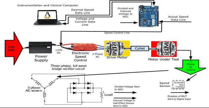
Figure 1: High Level Overview of Proposed System
Choice of Drive Motor
The team briefly considered using a permanent magnet DC (PMDC) motor as a candidate for the drive motor due to the simplicity of control, however these motors require a mechanical (i.e. brushed) means of commutation as well as large permanent magnets for motor action. Due to this electromechanical means of commutation as well as the weight associated with the large permanent magnets, the team decided against the use of a PMDC motor due to the prohibitively large size of the motor needed to meet the dynamometers demands. The sponsor has several brushless DC motors (BLDC) available, as such the team has decided to employ a provided BLDC motor to drive the MUT. A BLDC motor does not have the large permanent magnets of a PMDC motor, nor does it need mechanical commutation for motor action. The primary drawback of this motor choice lies with the sophisticated control circuitry required for motor action.
The popularity of BLDC motors has increased significantly in the last decade due to their high power to weight ratio and the lack of frictional losses due to electro-mechanical commutation. As such, there are several off the shelf control solutions, known as “electronic speed controls” (ESC) that, provided a base load of power, can invert a DC voltage into a three phase AC output to drive a BLDC motor. A pulse-width-modulated (PWM) signal is sent to the ESC and the frequency of the 3-Phase AC output is modulated to create the desired output (rotational speed of the rotor), from the provided PWM input.
Table 1: Motor Format Strengths.
Drive Motor Format |
||
Strengths |
PMDC |
BLDC |
Weight |
- |
X |
Size |
- |
X |
Ease of Control |
X |
- |
Efficiency |
- |
X |
Control Systems
Due to the team’s choice of employing a BLDC motor and using an off-the-shelf solution to control the motor, the team has little control over directly varying the voltage, frequency of commutation and current supplied to the motor. However, the team can take a reading of the speed at which the motor assembly is rotating and use this as a means of creating a first order control system with zero steady-state error and less than ten-second transient response to extreme system conditions. The device will lose some control precision, however past team experience with first-order control systems gives the team confidence in a first-order control systems ability to provide satisfactory steady-state and transient response.
Electronic Speed Control
The final decision for the ESC is still under consideration. The team desires to interface with a hobby-grade ESC intended for a remote control vehicle. The ESC in these devices serves to interface a receiver with a brushless motor. The receiver in a remote control vehicle communicates with the ESC through PWM. To prevent the spurious operation of the remote control vehicle, ESCs must be “armed” through the transmission of an “arm” signal. This “arm” signal is not the same between different ESC manufacturers. As such, the team is still finalizing their decision on an ESC that has power ratings commensurate with demands of the motor, as well as firmware that is open to modification.
Embedded System
An embedded system is required to implement the control algorithms as well as the data collection needs of the dynamometer. The team required an embedded system that has several on-board analog-to-digital converters (ADC), digital input and output (I/O), and an onboard interface for communicating with the control and instrumentation computer. Northern Arizona University includes the Texas Instruments MSP-430 frequently into its curriculum, so this embedded solution was taken into consideration for a considerable amount of time. However, the team is disappointed with the lack of GNU/Linux support in the development tool-chain for this device. As such the team has decided to employ the Arduino Leonardo as the embedded solution for this design. The Arduino Leonard has all of the onboard digital I/O and ADCs the team requires as well as an open-source friendly development tool-chain. Because the dynamometer is an open design that welcomes modification, the team decided that the high-level programming libraries available for the device that handle PWM, ADC control, and digital I/O would allow end users the simplest means possible for modifying the functionality of the dynamometer. Should a developer want more low level control of the device, an ATmega32u4 microprocessor lies at the heart of the system allowing a developer a wide range of programming options, from using Arduino sketches to bit-banging registers with assembly language, this device caters to developers of all skill levels, from novice to electrical engineer –a feature that is of paramount importance to this team and the overall success of the project.
Table 2: Embedded System Strengths.
Embedded System |
||
Strengths |
Arduino Leonardo |
MSP430 Launchpad |
Robust GNU/Linux Development Toolchain |
X |
- |
High Level Libraries for Experimentation |
X |
- |
Needed Functionality |
X |
X |
Power Delivery
The team has changed the power supply to a battery pack as a pragmatic decision to reduce complexity and cost. Power supply design is complex and the team does not have the intellectual resources to devote to this task. Purchasing an off-the-shelf unit that has the required capabilities is financially untenable. As such, the team has procured a 22.2V, 3000mAh battery and charger to conduct tests with. Additional batteries can be added in parallel to increase runtime, if needed.
Figure 2: Mechanical Stand Design
Sensors
Four motor characteristics are needed to meet the requirements of the device: dynamometer speed (i.e. the rotational speed of the coupled drive motor and MUT), voltage induced in the coils of the MUT, and current induced in the coils of the MUT. There are several means of measuring rotational speed (i.e., measuring the time between full rotations of the rotor). The first method uses an optical sensor and reflective tape on the rotor to induce a voltage change in an optical sensor. Another method is the use of a mechanical rotary encoder. The team was dissatisfied with these solutions due to the possibility of environmental disruptions and “misses” in the case of the optical encoder, and mechanical failure in the case of the rotary encoder. The team has decided to employ an ON Semiconductor NCV33039 Closed-Loop Brushless Motor Adaptor to read the voltage delivered to the motor. This IC can take a three-phase input, read the voltage applied to each phase of the motor, and send a TTL level “high” output when a rotation is complete. This IC allows the team a reliable means of digitally reading the speed of the motor when coupled with the embedded system. To read the voltage created by the motor under test, the team is choosing to employ voltage division coupled with ADC sampling across the load resistor. To read the current delivered to the load, the team is choosing to use a hollow core inductor or “Hall Effect Sensor” that will surround the wire delivering current to the load. Because the voltage induced in the inductor will vary proportionally to the current flowing in the load of the wire it surrounds, the team can use the second ADC on the provided embedded system to determine the current delivered to the load through reading the voltage induced across the inductor.
Test Stand
The stand material has been chosen from T-Slot aluminum material. This material facilitates the ease of construction and with the appropriate dimensions, the stand will endure any mechanical stress from the drive system.
- 10 series 1x3” and 24” long base will absorb motors torque and provide stability.
- 4 self-adjusting, leveling, vibration damping mounts will prevent vibration.
- 2 corner angle brackets holder with T-Nuts to mount motors (M1 & M2) to maintain positive control of the motors at maximum drive speed.
Resistive Load
As a team we came up with a MOSFET resistor load as seen below to drive the motor and test the different load conditions. However, we have encountered a problem where the MOSFET cannot operate in the cutoff and saturation regions due to a low input voltage. Then, we came up with op-amp (non-inverting amplifier) to boost the voltage until we get it operated in the required regions. In other word, the cutoff region needed to be 2 volt which means that when the input voltage is o volt, the op-amp output should be 2 volt to drive the gate of the MOSFET. On the other hand, when the input voltage is 5 volt, the op-amp output voltage should be 9 volt which is known as a saturation region.
Essentially, we chose the correct resistor values based on the below calculations:
Gain of non-inverting Amplifier = ![]()
Vout (That is required) = 9V
Vin = 5V
For the optimal current through the inverting terminal R1 = 1K
![]()
R1 = 800Ω
Closest actual Value of resistor is selected R1 = 820 Ω
R3 = 510 Ω which limits the voltage in negative direction.
The MOSFET transistor, here is used for the regulation of the voltages that is required at the output or in other words the voltages will not go beyond the thresh hold level and the transistor will act as a capacitor. This functionality is normally required for driving circuits.
The MOSFET in this circuit will store the voltages in the form of minute current and this current can be used for driving appliances such as motors in a controlled manner.
Figure 3: Active Load Schematic
Last Updated : 4/22/15