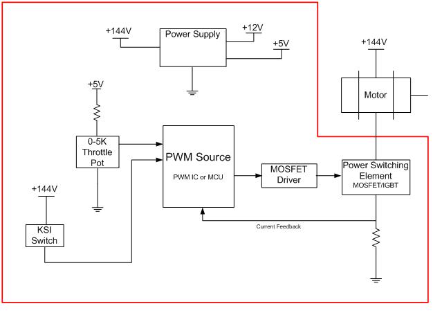
The ProjectProblem StatementThe team has been tasked to design a new motor controller for electric vehicles as part of the senior design capstone class [EE 486] at Northern Arizona University. This project started last year when preliminary research began on motor controls in the junior level design class [EE 386]. The research culminated into a small prototype circuit that drove a 12 Volt DC motor running at a nominal current of 33 milliamps. This year, the team hopes to build a much larger scale version of the prototype that was created in EE386. The new motor controller the team will design will power a DC brush motor at 160 volts and over 500 amps. In order to accurately test the motor controller on-road conditions, a vehicle will be converted to electric. The test vehicle is a 1994 Land Rover, Range Rover Classic that will give us the feedback needed to build a reliable and safe product. System DiagramThe following figure is a basic systems diagram of the motor controller and vehicle configuration.  The following figure is a block diagram of the motor controller device.  Requirements and SpecificationsThe following list of requirements and specifications was given to NAU Motor Systems by Electric Blue Motors: MechanicalThe mechanical requirements consist of size, weight, interconnect, and package. The controller must maintain these requirements. The size and weight deal with the controller. The interconnect deals with both the controller and the motor. The packaging is for the controller. • Size: Should be smaller than a Curtis motor controller. • Weight: Should not exceed 50 pounds • Interconnect: The motor controller must be able to power a 9” Brush DC motor. • Package: Packaging should incorporate a heat sink for MOSFET cooling and the controller will be packaged by the end of spring semester. ElectricalThe electrical requirements consist of power, and range. The power must maintain the voltage and the currents specified. The range must also be maintained. Power: The controller shall have an operational voltage of 96-144 V and the controller shall use at least 500 A. Ranges: The controller must be capable of a voltage range of 96-144 volts and at least 500A and the controller will implement a 0-5K throttle pot. EnvironmentThe environmental requirements consist of temperature, humidity, and vibrations/shock. The temperature is required to meet cold and hot. The humidity has to be considered in case the application is use where humidity is a factor. The vibrations/shock is a big factor. Temperature: The controller shall operate within a temperature range of -40 to 85 Deg-C. Humidity: The controller shall operate with a relative humidity range, of 10% to 90%. Vibrations, and Shock: Unit should handle vehicle vibrations. DocumentationMaintenance Manual: Manual will be done by April 30th. TestingThe testing requirements consist of procedures, and equipment. The procedures are for later use. The equipment must be tested regularly. Procedures: Procedures will be created for testing the controller and will be given to Electric Blue Motors for later use. Equipment: The controller will be tested every two weeks to make sure that it is functioning properly. GeneralThe general requirements consist of reliability, client preferences, and safety. Reliability is a must when working with vehicles. The preference is that it should be cheaper and easy to manufacture. The controller must be safe to the environment and to the people around it. Reliability: The controller must be reliable and have a mean time to fail rating. Client preferences: Unit must cost considerably less than either the Curtis Instruments 1231 C or LogiSystems 120-144V 750A controller( $1,500) and the unit must be easy to manufacture, should not take more than 10-man-hours. Safety: If the unit fails it should fail in a known and safe state that shuts down the output to the motor and the controller shall not emit hazardous radiation which could be detrimental to human health. |
|
Links |
Home | Members | The Project | Design Process | Pictures | Downloads | The Final Product | Sponsors | Contact Us |
|
Updated 04-14-2010 |
