 |
 |
 |
 |
 |
 |
 |
 |
 |
 |
 |
 |
 |
Design Document
Signature PageNathan F. Crary
Aasif Z. Syed
Amy J. Whitaker
Kevin Thornton
Client: Tom Kelleher, Conflict Simulation Lab, Lawrence Livermore
TEAM LIVERMORE
Design Document
EGR 486 CSE: Senior Capstone Design
Date of last revision: Nov 23, 1997
Revision number: 1.0
Table of Contents
1. Executive Summary 1.1 Description of Proposed Project
3. Preliminary Implementation Schedule
The Design Document is a detailed description of the proposed solution for the product requested by the Conflict Simulation Laboratory. The document will also serve as a guide to the implementation of the solution as well as the schedule for implementation.
The proposed project is to design a new tool which, utilizing Lawrence Livermore’s existing Conflict Simulation Laboratory code and simulation terrain map, will determine the optimal path between chosen starting and finishing points on a terrain map. The Conflict Simulation Laboratory’s code reports a weight, or "cost", for movement between any adjacent cells on the terrain map, based upon different criteria. By placing these costs together the optimal path from start to finish can be calculated and displayed to the user.
Work to be accomplished during the next semester is the development, integration, and testing of the different units that comprise the proposed solution. These units include the following:
- Route
- Area Costing Function Set
- Background Costing Function Set
- Costing Functions
- User Interface
In addition to these items, with time permitting, the items listed in the research section of the project proposal will be added. Primary among these items are the following:
- Decay Falloff vs. Radius on Area Costing Function Sets
- Limited Time of Duration of Area Costing Function Sets
- Design
- Preliminary Implementation Schedule
- Preliminary Test Plan
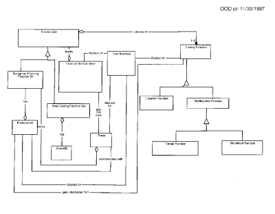
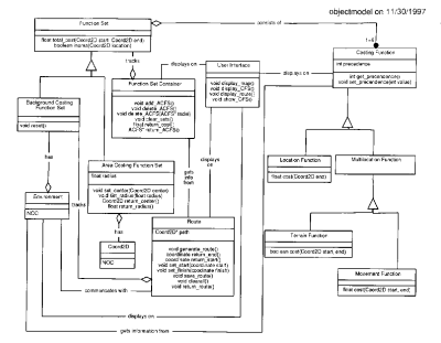
Primary function of the Function Set Container is to encapsulate all function sets and narrow the focus of the Route object.
The Costing Function hierarchy is broken up into four subclasses in two levels to encapsulate the functional requirements for the different costing functions.
The User Interface overlays all other objects, to allow easy removal of the functionality to be placed in the original simulator code.
2.2 Data Dictionary
AREA COSTING FUNCTION SET (ACFS) – FUNCTION SET that covers only a portion of the map contained within the ENVIRONMENT
BACKGROUND COSTING FUNCTION SET (BCFS) – FUNCTION SET that covers the entire map contained within the ENVIRONMENT
COORD2D – A Cartesian coordinate detailing X and Y positions on the map
COSTING FUNCTION – Individual functions that generate a portion of the cost to move between two points
ENVIRONMENT – Contains information on terrain and movement difficulty
FUNCTION SET – Superclass used to generate movement costs
FUNCTION SET CONTAINER – Adds, deletes, resets and reports costs of ACFS and BCFS
USER INTERFACE – Displays all relevant information to the users
LOCATION FUNCTION – Reports cost for a single location on the map
MULTILOCATION FUNCTION – Reports movement cost between two points
TERRAIN FUNCTION – Returns boolean information on whether the movement is allowed or not
MOVEMENT FUNCTION – Reports actual cost between two points
PRECEDENCE – A relative weighting for COSTING FUNCTIONS used in determining movement costs
ROUTE – Object that generates, saves, and displays route between two points
2.3 Architectural Diagrams
2.3.1 Object Model Diagram
The User Interface through its connections with Route, Function Set Container, Costing Function, and Environment objects gets all information necessary for display.
The Costing Function hierarchy is broken up into location functions and multilocation functions. Location functions, such as visibility and viewability, are functions that only require a single location as their parameter. Multilocation functions are broken up into the terrain function and movement functions. The terrain function returns a boolean value indicating the possibility of travel from a start location to an ending location. Movement functions also require a start location and an ending location, such as time and distance, but return an actual numeric value.
2.3.2 Dynamic Model Diagrams
2.3.2.1 Event Flow Diagram
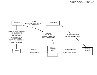
The data relations between objects represent two different message passing directions. The upper level on each relation represents data travel from the top or left to the bottom or right. Conversely, the lower level represents data travel from bottom or right to the top or left.
2.3.2.2 Event Trace Diagrams
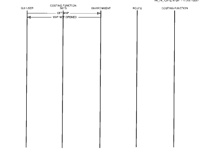
2.3.2.2.1 M_N_Open
This diagram shows the simple case where the terrain map cannot be opened.
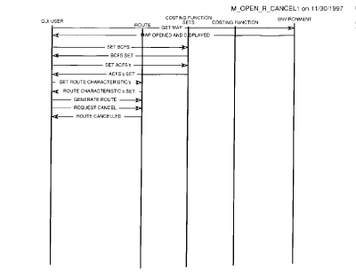
2.3.2.2.2 M_Open_R_Cancel1
This diagram shows a simplified representation of the user cancelling route generation.
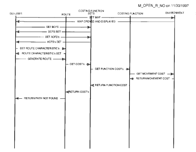
2.3.2.2.3 M_Open_R_No
In this scenario, a route cannot be generated given the information specified by the user.
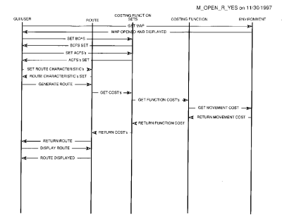
2.3.2.2.4 M_Open_R_Yes
This is the preferred scenario, where a route is generated and returned to the user.
2.3.2.3 State Transition Diagrams
Due to the nature of the project, these diagrams are closer to flow diagrams than state transition diagrams.
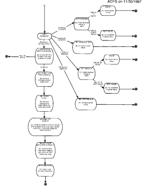
2.3.2.3.1 Area Costing Function Set (ACFS)
The Get Request state is used as an unofficial state, where the requests for information from the ACFS are processed.
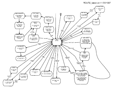
2.3.2.3.2 Route_latest
The Get Action state is used as a dummy state, where the requests for information from the ACFS are processed.
The state transitions can be broken into four types: basic, request route, clear all, and change. Basic includes requests such as Get Finish and Display Route, which consist of one transition from Get Action to the state and back. Change is only slightly more complicated, consisting of a validation step and then two states called Valid or Not Valid on the transition back to Get Action. Clear All is straight forward with transitions to each next state only dependant on successful completion of the action at the previous state. Request Route has a straight forward path, that is complicated by the capability of the user to cancel and return to Get Action at any state.
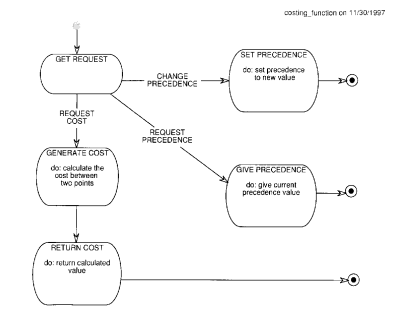
2.3.2.3.3 Costing_function
The Get Request state is an unofficial state used just to process requests and determine requested action.
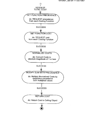
2.3.2.3.4 Function_set
The entire purpose of function set is to return the total cost of movement.
2.3.3 Functional Model Diagrams
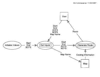
2.3.3.1 Llnl-functional
Top level view of functional model.
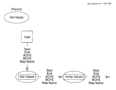
2.3.3.2 Get_Inputs
General view of getting and verifying values from user.
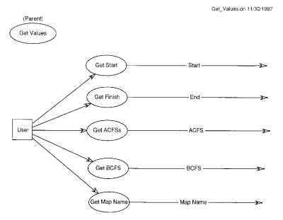
2.3.3.3 Get_Values
Zoomed view of value retrieval from user.
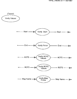
2.3.3.4 Verify_Values
Zoomed view of verification of received values.
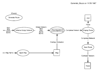
2.3.3.5 Generate_Route
Overview of process that includes generating, displaying, and saving route.
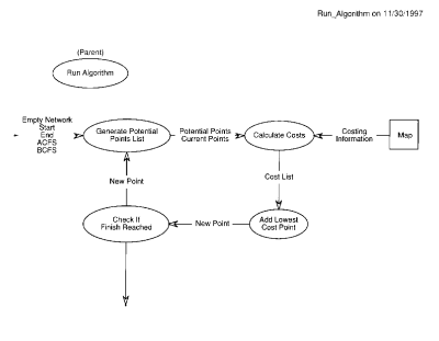
2.3.3.6 Run_Algorithm
Illustrates algorithmic loop for generating route.
These schedules reflect only the development and testing of the project code. Once all other deadlines and milestones are known, they will be added to create a detailed schedule for next semester.
3.1 MS Project Gantt Chart
See Gantt chart.
3.2 MS Project PERT Chart
See PERT chart.
3.3 MS Project Resource Loading Sheet
See Resource sheet.
The following tables represent the stage in which each specification will be tested. The three different stages of testing are at the Unit, Integration, and System levels. The Unit level tests the functionality at a very detailed level, such as a function. The Integration level tests the functionality of several units interacting together. Lastly, the System level tests the functionality of all integration levels within the system interacting with each other.
Following each table is a brief paragraph describing the methods that will be used at each stage of testing. The testing method will be the same for each specification within the test strategy.
4.1 White-Box Test Strategy
|
Specification Number |
Test Stage |
| 2.2.1 | N/A |
| 2.1.2a | N/A |
| 2.1.2b | Unit, Integration, System |
| 2.1.3a | Unit |
| 2.1.3b | Unit |
| 2.1.3c | Unit |
| 2.1.3d | Unit |
| 2.1.3e | Unit |
| 2.1.4a | N/A |
| 2.1.4b | N/A |
| 2.2.1 | Unit |
| 2.2.2 | Unit |
| 2.2.2.1a | N/A |
| 2.2.2.1b | N/A |
| 2.2.2.1c | Unit |
| 2.2.2.2a | Unit |
| 2.2.2.2b | N/A |
| 2.2.2.2c | Unit |
| 2.2.2.2d | Unit |
| 2.2.2.2e | Unit |
The White-Box testing method used for this project will be the Basis Path method using flow graph notation. Flow graphs easily illustrate the control flow through each function or stage. These illustrations allow for detailed testing at all levels, but are most effectively used in unit testing.
4.2 Black-Box Test Strategy
|
Specification Number |
Test Stage |
| 2.2.1 | Integration, System |
| 2.1.2a | Integration, System |
| 2.1.2b | Unit, Integration, System |
| 2.1.3a | Integration, System |
| 2.1.3b | Integration, System |
| 2.1.3c | Integration, System |
| 2.1.3d | Integration, System |
| 2.1.3e | Integration, System |
| 2.1.4a | Unit, Integration, System |
| 2.1.4b | Unit, Integration, System |
| 2.2.1 | N/A |
| 2.2.2 | Unit, Integration, System |
| 2.2.2.1a | Unit, Integration, System |
| 2.2.2.1b | Integration, System |
| 2.2.2.1c | Integration, System |
| 2.2.2.2a | Integration, System |
| 2.2.2.2b | Integration, System |
| 2.2.2.2c | N/A |
| 2.2.2.2d | Integration, System |
| 2.2.2.2e | Integration, System |
The Black-Box method used for this project will be Equivalence Partitioning. Equivalence Partitioning allows for several different input cases in which half the cases are valid inputs and the other half are invalid inputs. This will ensure that all specifications receive the appropriate input and can determine invalid input.
