Modular Configuration Testing
The purpose of the modular configuration testing is to determine the removal efficiency of a series of materials. The modular configuration device was designed with ease of maintenance in mind. Each material was placed in a separate module (or compartment), with the ability to detach from the system in order to perform maintenance or replace one material at a time. Four different modular configurations were selected for testing, as shown in the summary of results below.
Selection of Materials for Modular Configurations
The materials to be tested in the modular configuration were determined by the results of the column tests. A summary of these results can be seen here.
While the ion exchange resin proves effective for both uranium and arsenic removal, it is not included in the configuration testing for three reasons. First, because ion exchange resins are engineered to work, there is little question of their success. Second, if an ion exchange resin is placed in series with other materials, the results for the efficiency of the system may potentially be based primarily upon the removal efficiency of the ion exchange resin, as it will be able to remove the uranium and arsenic that the other materials in the series may not. Third, this project seeks to use low-cost and innovative solutions. Ion exchange resins are known to work, but are not necessarily innovative or low-cost. Therefore, the modular configurations focus on the use of orange peels, ZVI filings, and ZVI turnings. Orange peels are selected for their ability to remove uranium, ZVI filings are selected for their ability to remove both uranium and arsenic, and ZVI turnings are selected for their ability to remove arsenic . Rice husks are eliminated because they are not able to remove uranium or arsenic . The criteria for material selections is based only upon the effectiveness of the material to remove either uranium or arsenic.
Detailed Results of Configuration Tests
To see the detailed results of the configuration tests, click on the title of the Configuration. Each table of results presents the concentrations of uranium and arsenic for the effluent from the column. When the value is shown in red, this indicates a failure of the configuration to reduce the contaminant to below the maximum contaminant limit. When the value is shown in green, this indicates a success.
Configuration #1: ZVI Filings Followed by Orange Peels
Configuration #2: Orange Peels Followed by ZVI Filings
Configuration #3: Orange Peels Followed by ZVI Turnings
Configuration #4: ZVI Turnings Followed by Orange Peels
Comparison of All Configurations
Procedure for Configuration Testing
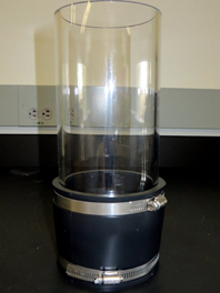
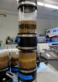
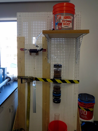
The experimental filtration device, depicted below, consists of two modules containing the filtration and support media. The module housing consists of a 4.75 inch outer diameter clear acrylic tubing with an inner diameter of 4.20 inches. 120 mesh screening is fixed to the bottom of each module with epoxy. This prevents the washout of any materials and provides additional support for the module materials. The modules are held together by a 4 inch x 5.25 inch in-line rubber coupling secured using 0.5 inch wide and 1/16 inch thick steel adjustable pipe clamps. The rubber coupling has a thickness of 0.5 inch and allows for a tight seal between the acrylic tubing. The use of couplings in the design allows for easy access to the materials. This allows users to perform maintenance, material replacement and breakthrough monitoring. 5.25 inch x 2.5 inch rubber caps with a thickness of 0.5 inch are used at both the top and bottom of the device. Additionally, 1 inch nylon nozzles are attached to these caps to allow for the inflow and outflow of contaminated and treated water. To guarantee a tight seal at the nozzles, two 0.475 inch rubber washers are placed on each side of the rubber caps. The nozzles are held in place by a nylon retaining nut. The modular system is connected to an elevated reservoir via plastic tubing. The flow rate is controlled by a ball valve.


From Left to Right- One Empty Module, Two Modules Connected by Rubber Couplings, Configuration Connected to Reservoir and Ready for Testing
The experimental procedure for the modular configurations is as follows:
- Fill each module with approximately 4 inches of gravel so the sand and material starts at the visible portion of the acrylic column. The gravel prevents the sand and materials from clogging or filtering through the screen at the bottom of the module.
- Place the appropriate sand and material quantities on top of the gravel.
- Connect the modules in the order desired with the rubber couplings.
- Connect the modular system to the tubing and reservoir system.
- Place a 1 L or larger graduated cylinder under the apparatus to collect effluent.
- Allow approximately 1 L of DI water to flow through the system to ensure it is operating properly and to completely saturate the materials.
- Use a pump to fill the reservoir with approximately 12 L of synthetic water.
- Allow the synthetic water to flow through the modular system while maintaining a constant head of water on top of the material in the first module.
- Collect the effluent in the graduated cylinder as it exits the system. After 2.5 L has accumulated in the cylinder, pour the effluent into a clean container.
- Use the effluent in the container to fill one centrifuge tube to send for U and As analysis. Use the remaining effluent in the container to test for pH, turbidity, total dissolved solids, and dissolved oxygen.
- Repeat steps 9 and 10 after 5 L, 7.5 L, and 10 L has flowed through the system.