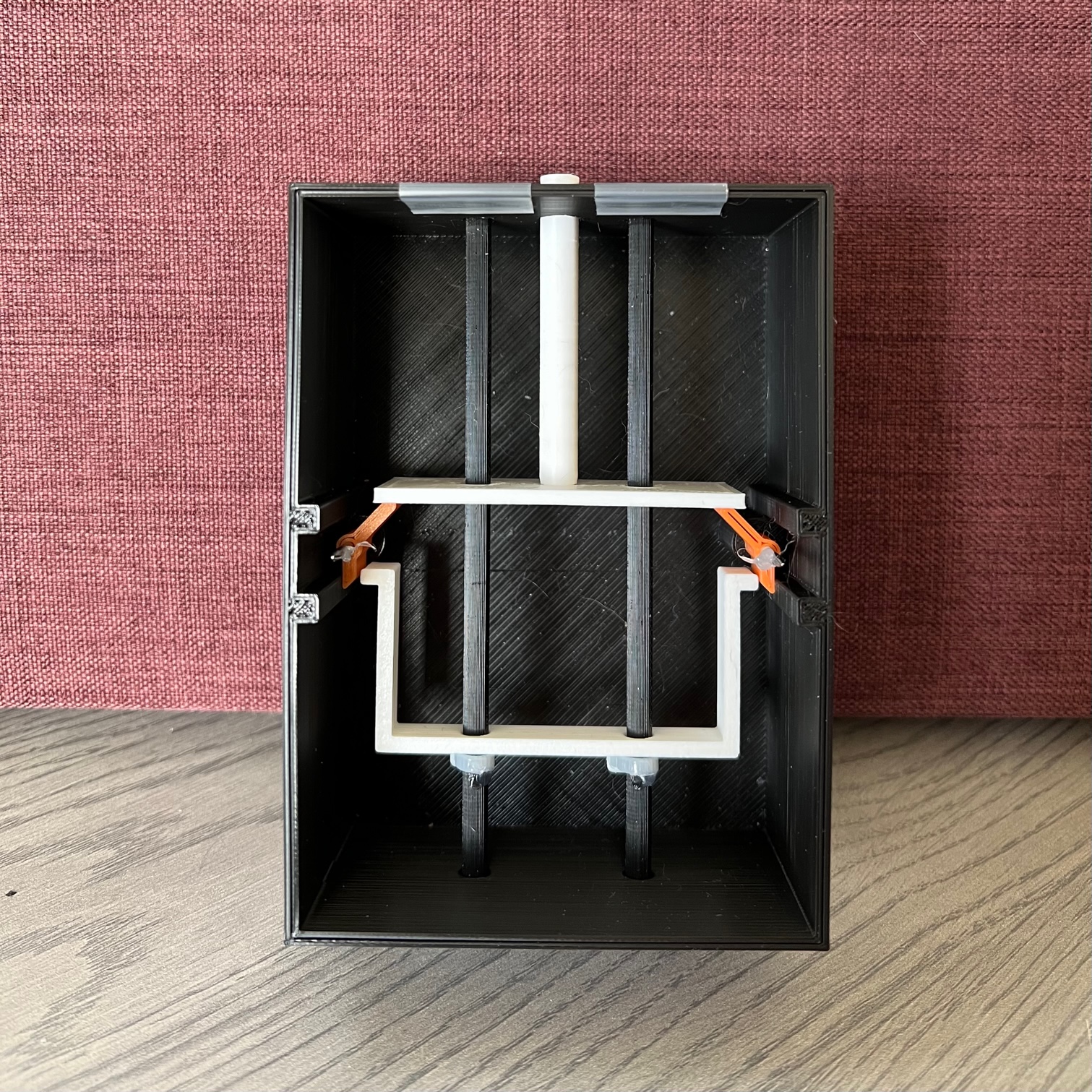
Figure 1: Initial Prototype Gate-lock
This model was the first physical demonstration of our design; as such it was not functional. It served as a visual aid for presenting the mechanism that drives our HDRM design. This desing is further explained in the preliminary report.
Created: 3.30.22
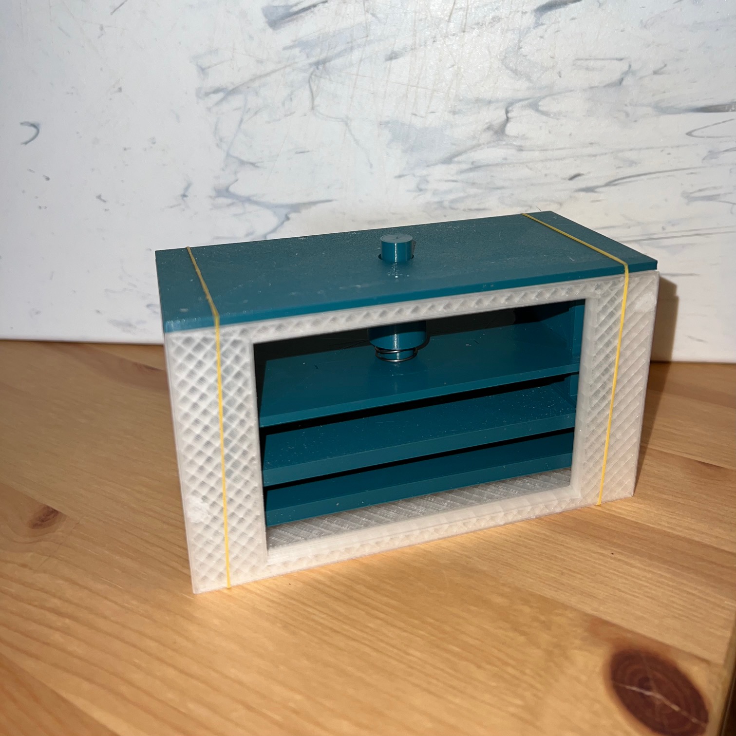
Figure 2: Lock iteration: Ball-lock version 1 - Upper view
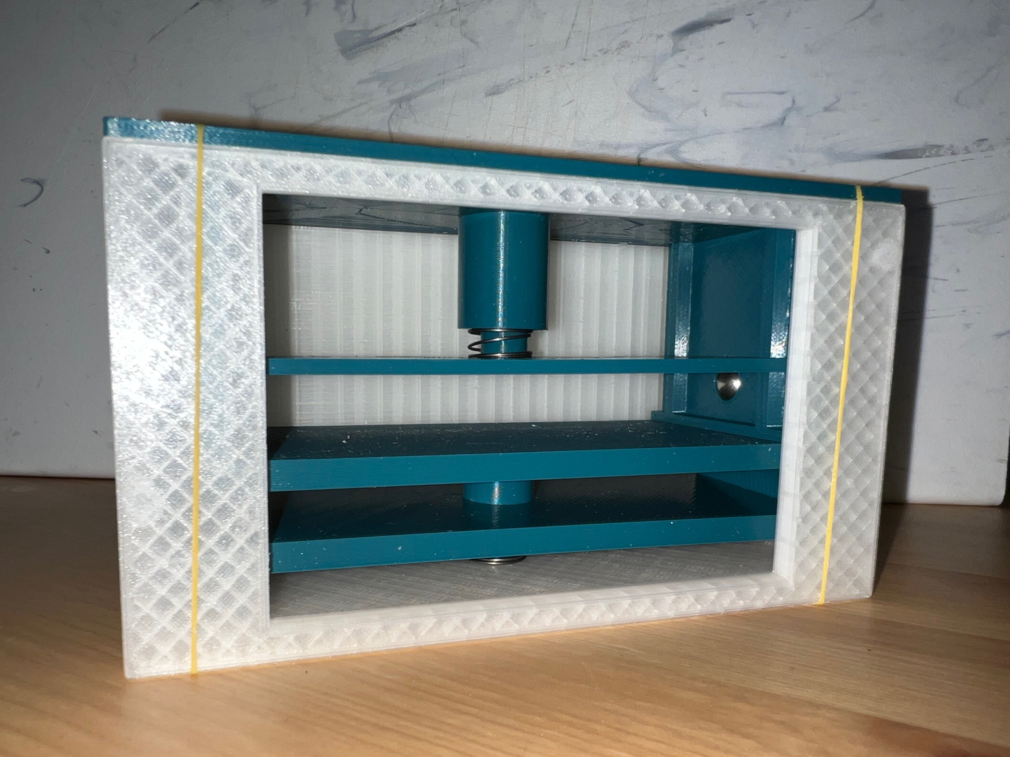
Figure 3: Lock iteration: Ball-lock version 1 - Internal view
This design in figures 2 and 3 uses similar mechanics and subsystems as the previous prototype, but replaces the gate-style lock mechanism with a locking system using ball bearings. This prototype, although large and rough, functions as long as the user manually moves the lock out of place. This design is further explained in the engineering analysis reports and the final report (CDR).
Created: 4.15.22
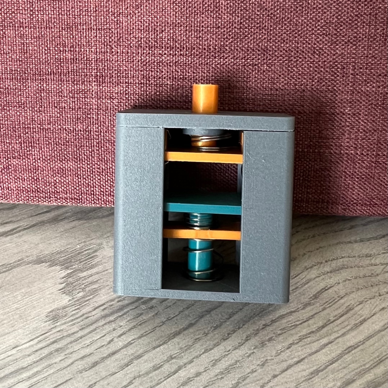
Figure 4: Ball-Lock design version 2
This is the same mechanism as shown in figures 2 and 3, but downsized and improved geometrically and in quality with respect to the 3-d printing manufacturing process. Where the ball-lock version 1 had a volume around 30 cu. in., this iteration only takes up 4 cu.in.
Created: 4.22.22
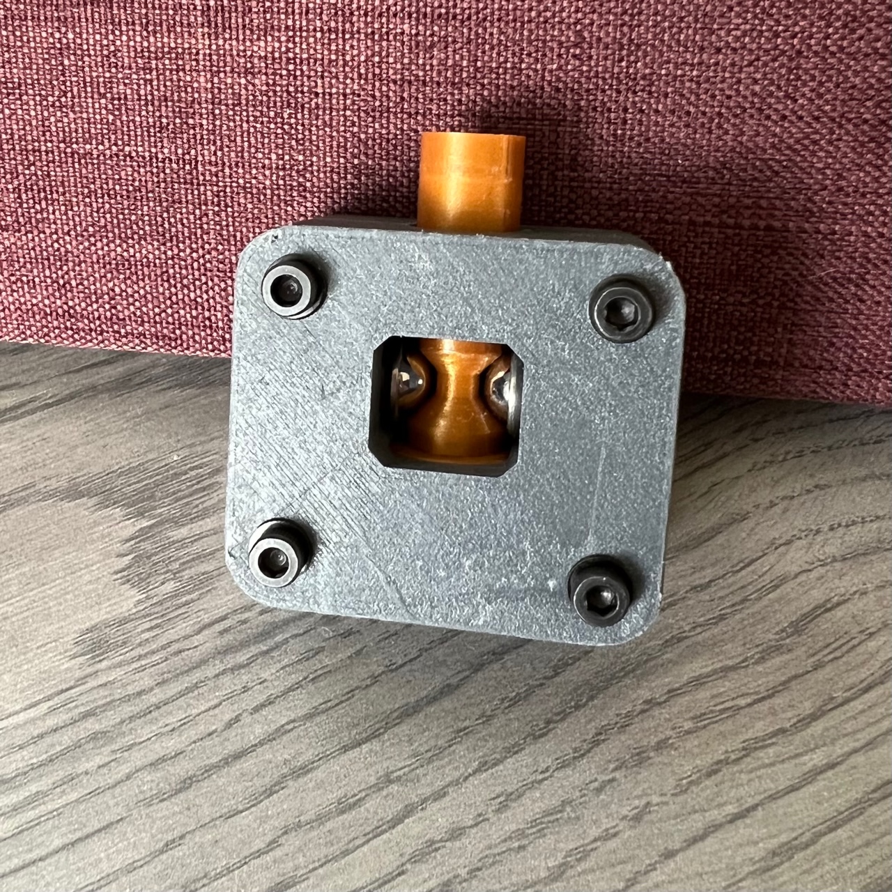
Figure 5: Design experiment: Detent system - open configuration
This design has not been discussed in any documents as of 4/26/22. It is an alternate HDRM design based on detent versus an actual lock. In other words, the pin in this design is pulled in by forcing it to overcome the detent force biasing it into its open position. This is different from the official final design as of 4/26/22 because the final design (figures 2-4) does not allow the pin to be forced inwards, as it is a *locking* design, not a *detent* design.
Created: 4.24.22
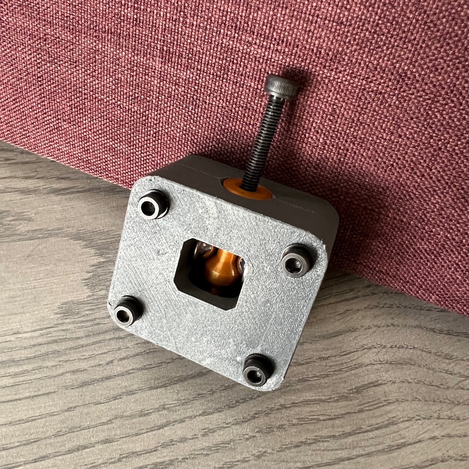
Figure 6: Design Experiment: Detent system - Deployed configuration
This shows the same design as figure 5, but the pin has been forced into the device. A 3mm metric screw is used to thread into the pin to pull it back out into open position.
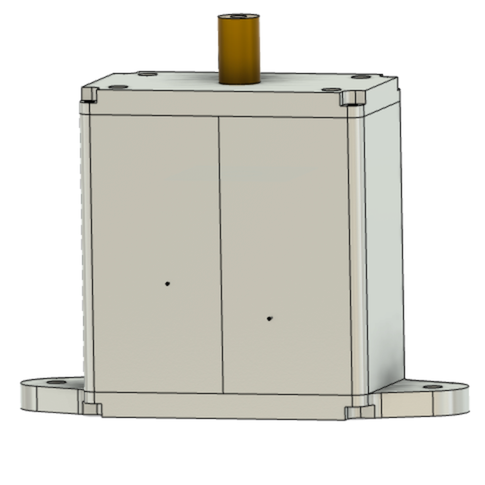
Figure 7: Final Design for Manufacturing - Closed
This is the final design of the ball-lock design; it is optimized geometrically and redesigned for manufacturability and assembly. This figure shows the model with the shell in place.
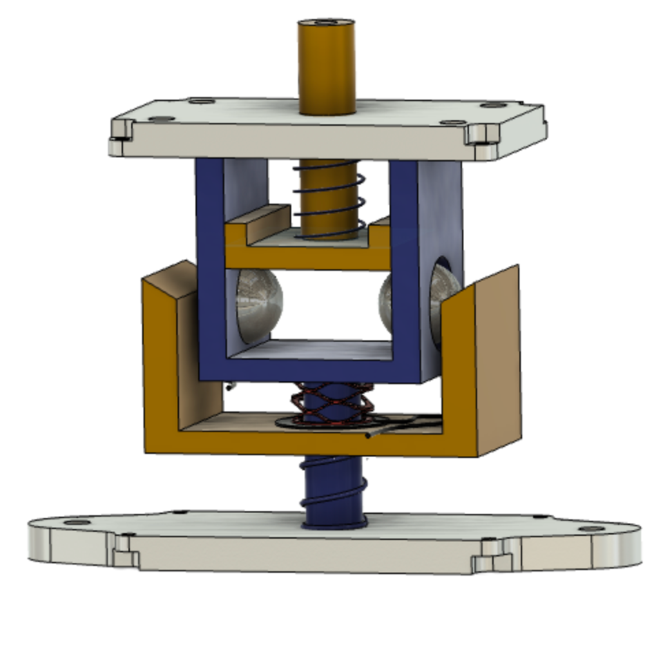
Figure 8: Final Design for Manufacturing - Open
This is the final design of the ball-lock design; it is optimized geometrically and redesigned for manufacturability and assembly. This figure shows the model with the shell removed to see the internals.
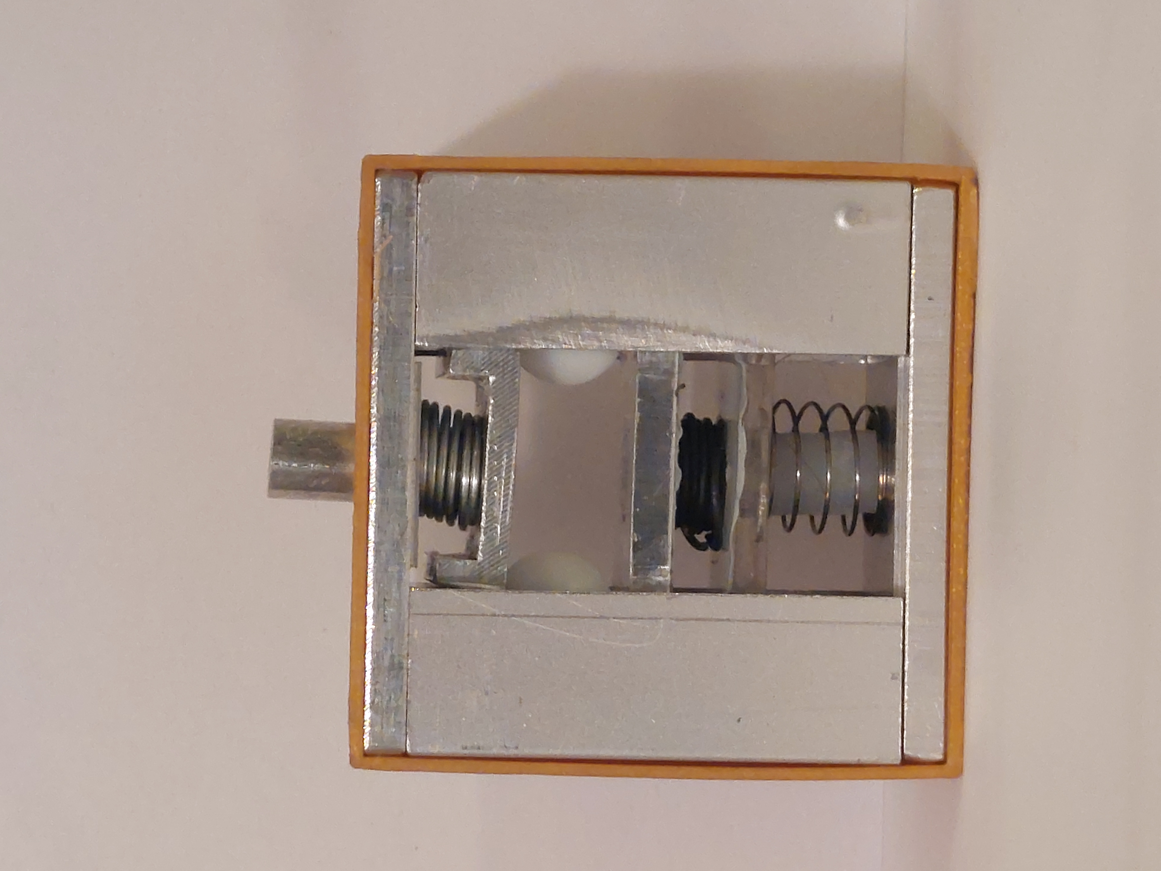
Figure 9: Final Manufactured Model
Pictured above is the final model manufactured at the NAU fabrication machine shop and the IDEA lab. most parts have been created on the manual mill and manual lathe, however one part was created in a CNC machine and two parts were 3D Printed.
Created: 11.11.22
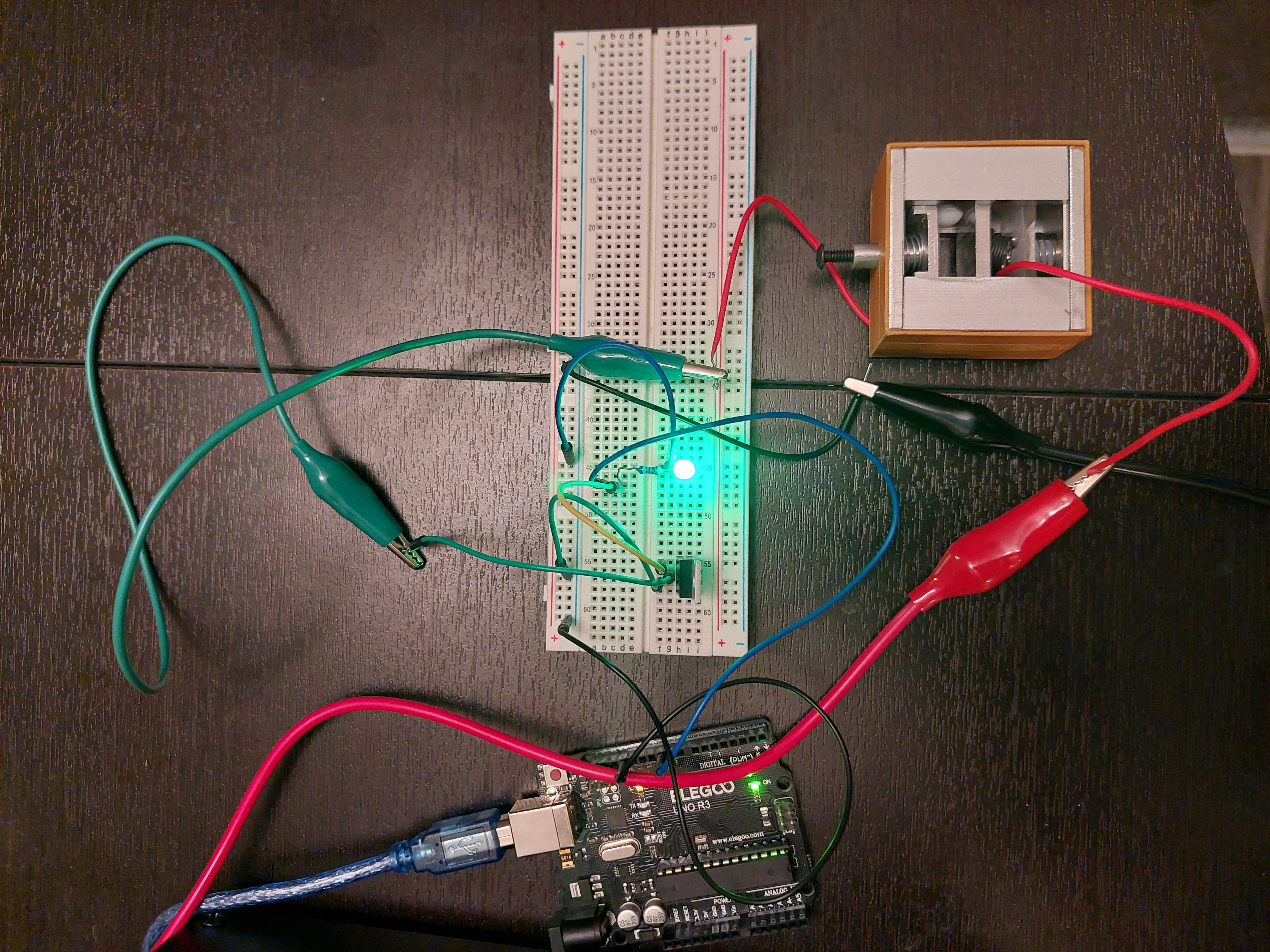
Figure 10: Manufactured HDRM Connected to Power Supply
Pictured above is the final manufactured model once it is connected to the PWM circuit. This circuit supplies alternating current to the device to prolong the life of the Nitinol SMA spring.
Created: 11.11.22
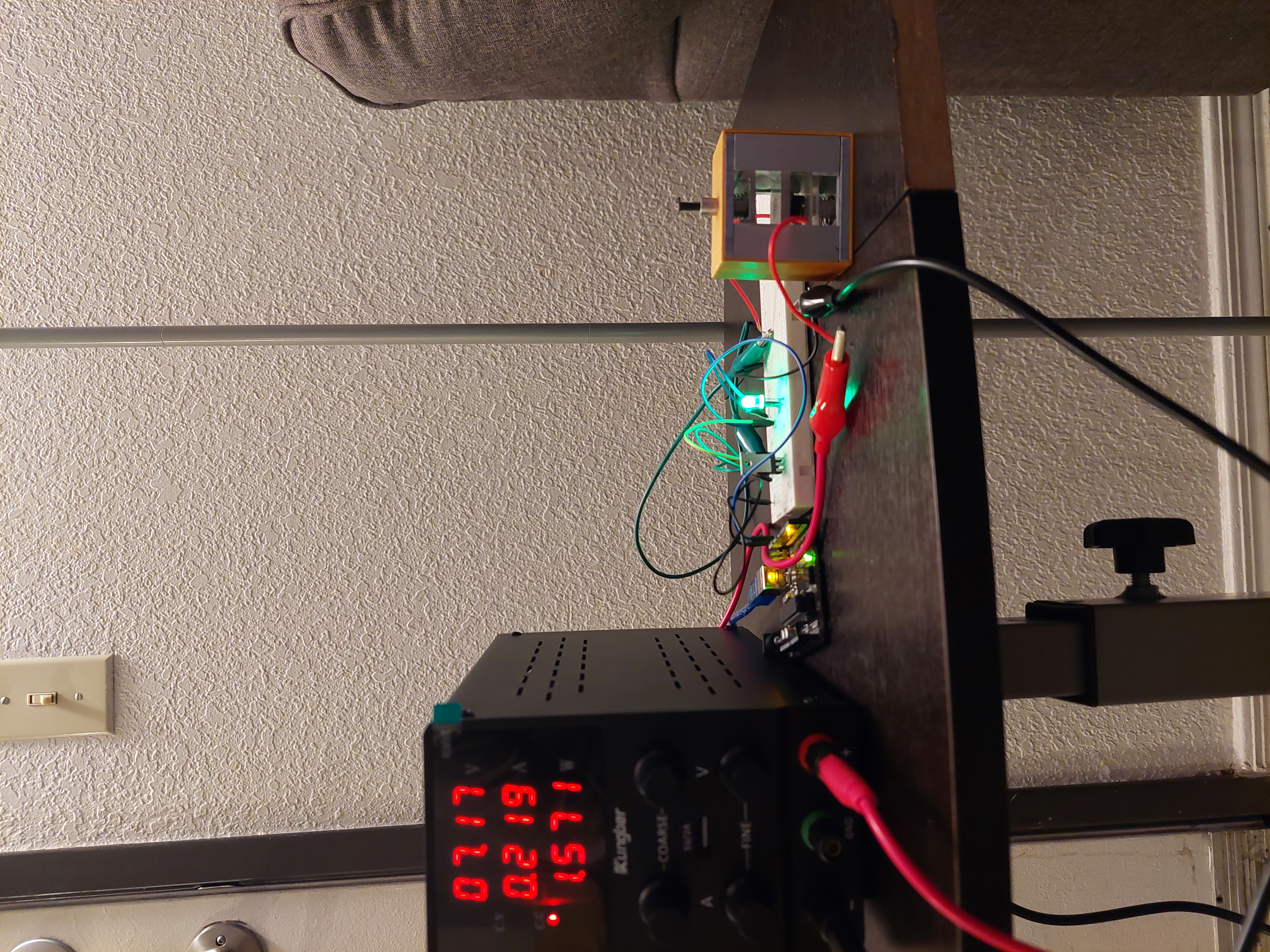
Figure 11: HDRM Connected to Power Supply
Alternate angle of figure 10; power supply unit can be seen in the photo.
Created: 11.11.22
Demo Video of Nitinol Expanding with Heat
The video in this link demonstrates how Nitinol reacts when heated with electric current.
Demo Video of the Manufactured HDRM Actuating
The video in this link demonstrates the HDRM connected to the power source and circuit. The device is actuated with the heat generated from electric current.