Designs Considered
This page is an overview of the designs initially considered by the team. The final design is shown on the home page.

Spring propulsion design
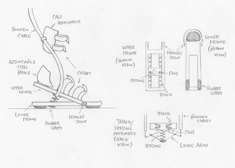
This design provides an assistive propulsive force using a spring attached to the bottom of the foot. Attached to the spring are lever arms, the outer ends of which connect to the Bowden cables. When the motors (which attach at the waist) engage, the cables are tensioned, and the spring compresses. The cables are then released, and the spring recovers to its free length, thus supplying a force to the ground, and propelling the foot forward. The exoskeleton device consists of an upper frame, which features a track along which the spring assembly can be positioned, and a lower frame, which provides support at the toe. The upper plate is hinged to the lower plate at the ball of the foot. Analysis of this system proved that the design was not feasible (due to the required spring sizes), and the design was therefore discarded.

Direct-pull design
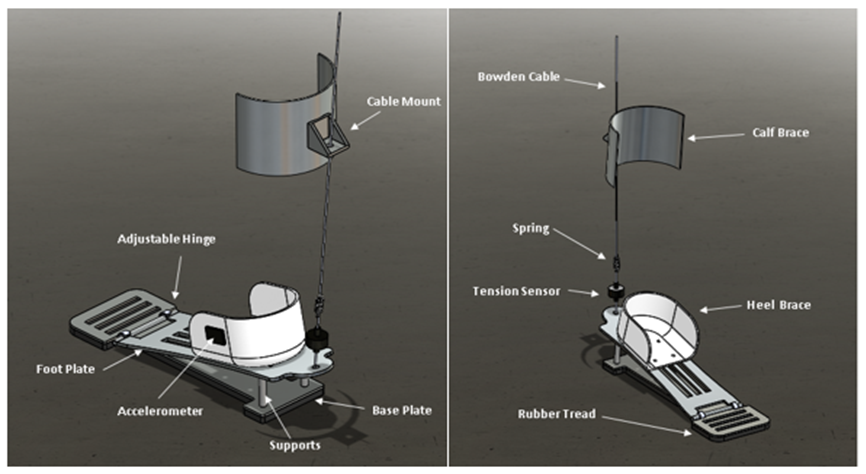
This design provides propulsion directly at the heel. The Bowden cables, powered by motors at the waist, provide a tensile force at the rear of the foot plate. The foot plate is hinged to the base plate, allowing the foot plate to rotate. The cables are mounted to a calf attachment. An adjustable heel brace and adjustable supports at the rear of the base plate provide scalability for a range of equinus deformities. This design ultimately proved unable to provide rotation due to lack of ankle motion, and as a result could not provide propulsion.

Lever arm design
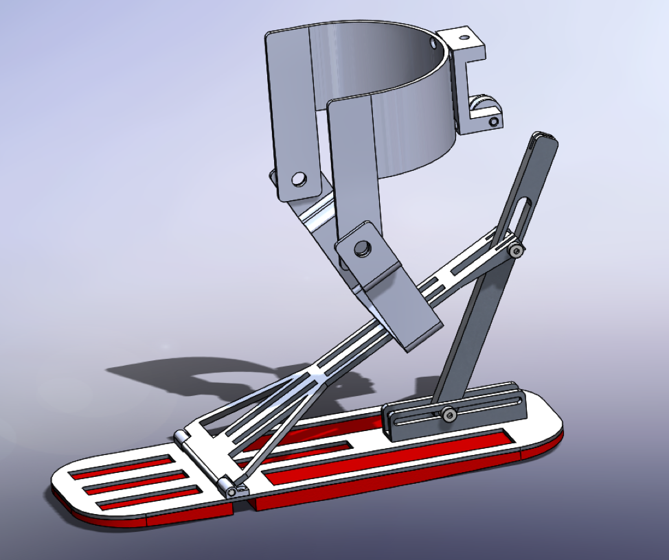
This design provides propulsion through an adjustable lever arm at the heel. The lower end of the lever arm hinges to a track along the rear of the base plate (the track provides adjustability for the lever arm). A slot in the lever arm is pinned to the rear of the foot plate. The upper end of the lever arm attaches to a Bowden cable. When the motors (attached at the waist) engage, the cables are tensioned, pulling the upper end of the lever arm upward and forward. The arm rotates about its lower end (pinned to the track on the base plate), and the arm pushes the foot plate upwards, thus providing propulsive force to the foot. The foot plate is hinged to the base plate at the ball of the foot, allowing for rotation. An adjustable U-bracket attaches to the foot plate and connects to a calf attachment. At the rear of the calf attachment is a mount for the cable, which features a pulley (to allow for the cable to attach perpendicularly to the lever arm). This design, while it provided the necessary motion, contained significant frictional losses and control limitations.

