Design
The designs presented here include the gasket, latches, handle, tie downs, floor, and hinge.
Gasket Design:
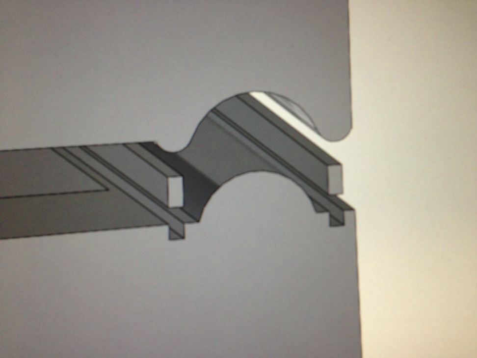
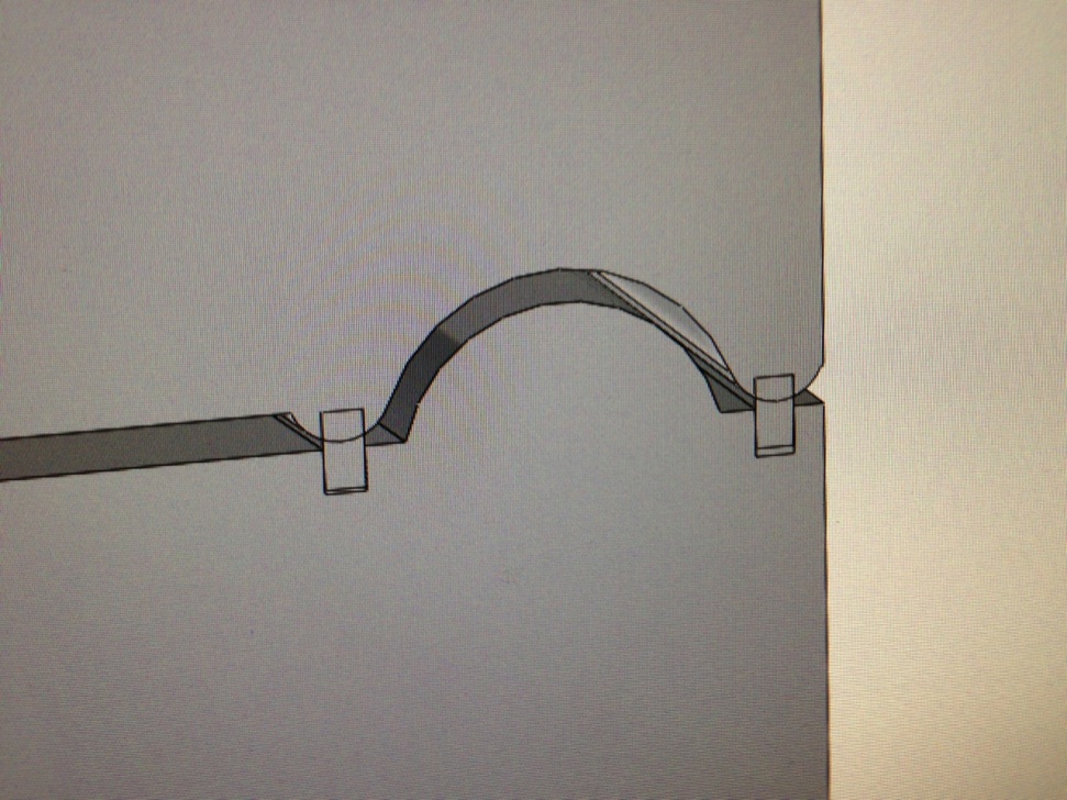
The gasket layout has two foam seals that are meant to trap air in between. By doing so, we are planning on significantly reduce the rate of heat transfer trough the seals, therefore minimizing the overall rate of heat transfer for the entire assembly. The goal is to offer redundancy features as well, by doing so the entire assembly will not be totally compromised in case of the failure of one of the foam seals. The only change the team might make on the CAD model is the shape and size of the foam seals, since these components are extremely cheap and utilizing better ones would not end up affecting the cost of the final product significantly. Figure 1 depicts the exploded view of the gasket assembly and Figure 2 shows the design in its compact form.
This design will wrap the entire perimeter of the cooler. It can be noticed in Figure 2 below that the design conflicts with itself in the meshing of the top and bottom. The plan is to expand the width of the foam strips to improve the mesh.
Latch Design:
The main focus in designing this latch was to make it backwards compatible with the existing design. This means our design functions in the same basic way, with a single rivet in the top driving the latch into the cooler lid, and a male knob screwed into the cooler body where the female attachment on the latch secures. The specifics of the design can be seen in Figure 3 below.
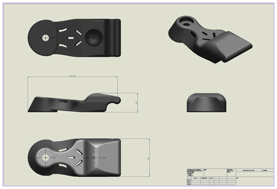
The design features a tapered shape on all sides to help reduce its surface area, which makes the design less prone to catch on other objects when in use. The lower part of the latch was design with the human hand in mind. It is ergonomically shaped to allow the palm to apply downward pressure for latching and to allow the use of a single finger to undo the latch. The cut outs in the design are strategically positioned to allow the latch to stretch and flex without inducing excessive stress concentrations. The group is doing research on various forms of nitrile rubber as the main candidate for the latch material. The stress analysis done on this component can be seen in the experimental portion of this report.
Handle Design:
The handle mechanism itself will be purchased wholesale from an existing distributer. It consists of a strong nylon rope and a cheap plastic handle that is threaded onto the rope. The rope is fixed to the cooler through a system of knots. The part that the team designed was the specifics of this attachment. The design is shown below in Figure 4.
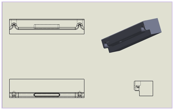
The top left corner is the front view of the design, bottom left is the bottom, bottom right is the side view, and the top left is the isometric view. This is located on each side of the cooler body on the lower lip. The wide holes on the top of the design will recess the rope knot into the cooler body reducing the overall projected footprint of the cooler. The two channels will guide the rope and secure it into place as the user lifts the ice chest. They will also reduce the overall distance the rope has to travel therefore saving material and reducing cost. The cut out in the center of the design is an additional fixed handle that provides the user with a couple options for transporting the device. One disadvantage of this design is the possibility of the recessed holes collecting debris and facilitating wear on the rope. This problem will be addressed in the future.
Tie Down Design:
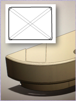
This feature allows the user to secure the cooler in a wide range of configurations for different purposes. The main advantages of the design are its ability to fix the cooler body to a surface while keeping the lid free to open and close maintaining functionality. The lid can also be fixed in place to improve seal and keep out intruders of the human or animal variety. The design is depicted below in Figure 5.
Floor Design:
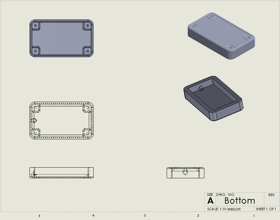
The bottom of the cooler has a few features worth mentioning. First of all the roto-molding and insulation injection process calls for four holes along the outside of the cooler and this makes perfect standardized holes for rubber feet and there are already standardized rubber feat available. Around these holes we have recesses so the cooler will slide easily when tilted. Also this protects the rubber feet from high shear stresses when dragged along an irregular surface. The drain plug is a standard 1” inch hole lofted into the inner chamber of the cooler to allow for easy drainage
.
Hinge Design:
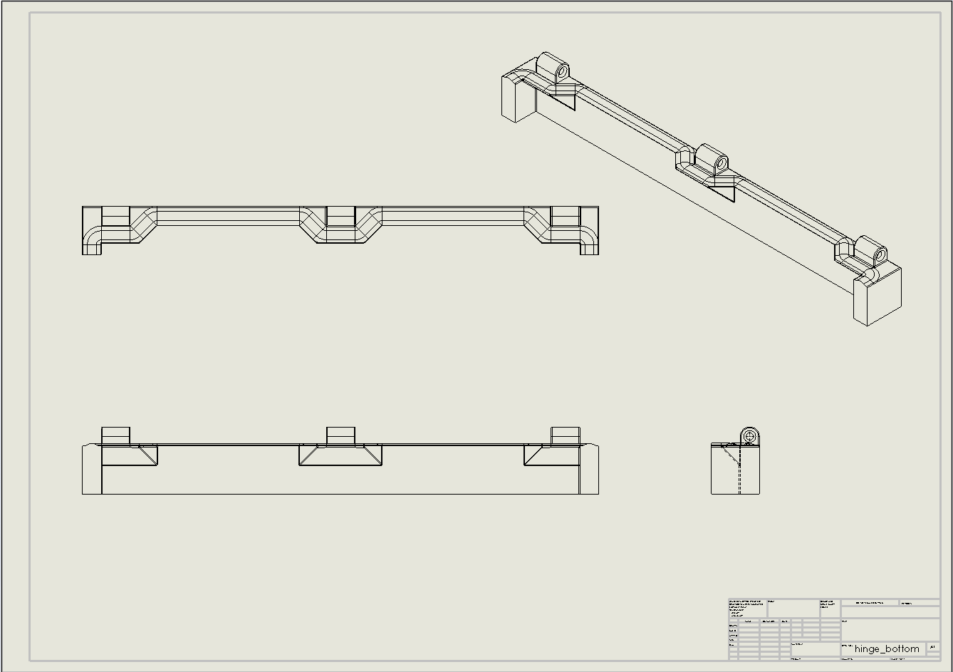
The requirements of the hinge are that it open and close easily, add durability to the lid of the cooler to prevent warping, create a firm and consistent seal between the lid and the body and open flat against a wall when open. Currently, this last requirement is proving to be the most challenging. The current design allows for this but has very tall hinges on the body, creating stress points and promoting fatigue in the ears on the body. A design is currently being modeled using Solid Works to combat this and is still in progress. Figure 7 below depicts the current design for the hinge. Changes are constantly being made to this design to improve it. The final design will open flat against the back and provide a very tight seal as well as allow for easy opening and closing.
