Wind Tunnel Testing
Initially the team planned on using a wind tunnel and force balance at Embry Riddle. Unfortunately, due to scheduling issues, we were not able to use their wind tunnel or equipment. This is what led to the design and construction of a custom force balance. The wind tunnel test section and mounting points were measured and modeled in SolidWorks so the mount could be designed around them. Then the mount and force balance were designed to fit the NAU wind tunnel dimensions. The Road surface and force balance designs are shown below in Figure 3.
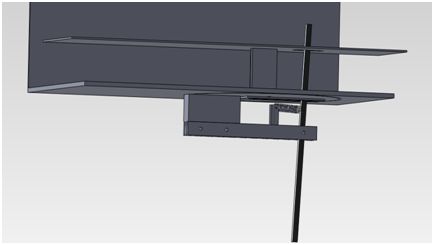
Figure 3- SolidWorks design of force balance and road surface
Next the team created part drawings and began machining the various components of the system. Finally we were able to test our model in the wind tunnel using the custom displacement force balance. As you can see in Figure 4 below, the main lever arm is constructed of a light plastic. This gives the lever arm a smaller moment of inertia so it will have little effects on the force measurement and will respond quickly to changes.
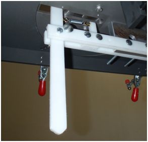
Figure 4- Photo of force balance attached to wind tunnel
The second portion of the design consists of the modeled road on which the semi rolls. The base of the road mounts inside the wind tunnel to existing bolt holes in the test section. Then there is a raised flat plat attached to the mount which simulates the road. Although there is still a boundary layer created on the flat plate, by placing the semi at the very front edge of the plate, the boundary layer is minimized. The road mount can be seen below in Figure 5.
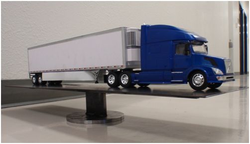
Figure 5- Scale model tractor trailer on wind tunnel roadway
Wind Tunnel Results
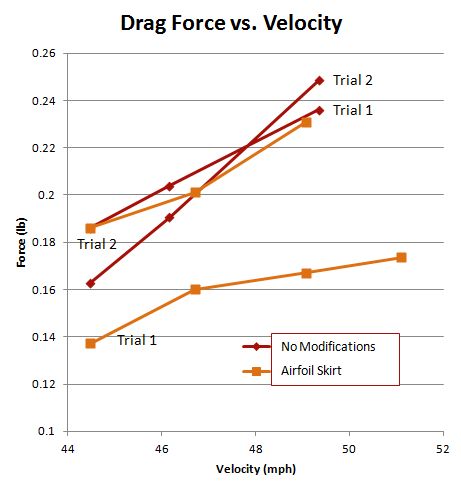
Figure 6- Wind tunnel results showing drag versuswind speed
The results gained in this wind tunnel experiment are not accurate enough to warrant extrapolation of force to a full scale semi truck. Though, when multiple trials were conducted, the results could be used as a comparison. As you can see in Figure 7 below, the Airfoil Skirt faring was shown to reduce drag in both SolidWorks and the wind tunnel test.

Figure 7- Comparison of drag reduction between wind tunnel tests and SolidWorks
Final Design
After both SolidWorks Flow Simulation and wind tunnel tests at NAU, our team has verified that the Airfoil Skirt fairing is the best performing design. The design is also very well suited for manufacturing. The extruded 2D shape lends well to the use of pre-cut sheets of polymer which would be heat formed around a profile or mold of the shape. The amount of material required is also very minimal as compared to the other designs. Having two separate skirts, allows tractor trailer owners with conventional side skirts to keep one side and only replace the side skirt that houses the battery box.
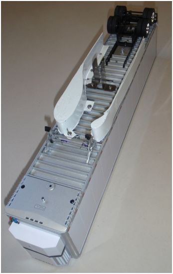
Figure 8- Final Design Prototype
Wind Tunnel Test Improvements
Our team has come up with a number of reasons for the large amount of variability in the wind tunnel results. We believe most of the problems stem from the fact that the model must roll to indicate a specific force value. With the use of this rolling technique, the following issues would have a significant and detrimental effect on our results:
- Bent axle
- Non-circular wheels
- Uneven rolling surface
- Inertial effects
One easy method for increasing the accuracy of our force balance would be to use a load cell or strain gage in place of the spring. Because these two measurement devices only displace microscopically, the issues related to rolling could all be mitigated. Another place where there is room for improvement is in test section size. The 1/32 scale model which was used was slightly too large for the test section size we had available to us. Using a wind tunnel with the correct test section size would also increase the accuracy of our results.
