Fairing Designs
Many of the design decisions for the fairing design were based on the team’s understanding of aerodynamics. Below is a list of the various fairings that the team designed and tested in SolidWorks.
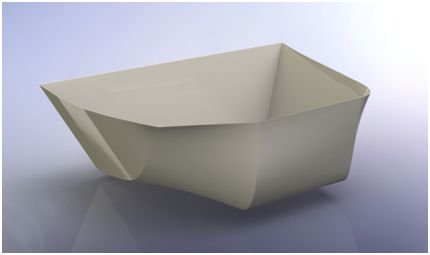
Boat Nose Fairing
This design is based on a deep-v boat hull. The concept is to split the air which flows under the tractor and send it out to the sides of the trailer. The underside of the trailer is a turbulent area due to all the I-beam cross members which disrupt the flow. The design separates streams of air which make it past the landing gear and sends them to the outside of the trailer, as well as pushes the air away from the rough surface of the trailer underbody and towards the roadway.
Filleted Fairing
This fairing employs the concept that a tear drop will eliminate the separation of slip streams behind an object. The goal with this design is to bring the air that has come from under the truck and let it flow up from the ground, creating the least amount of turbulence behind the battery mount cover. The front of the fairing is made to mesh with the landing gear in order to create a circular flow in between the rear end of the truck and the landing gear. This circular flow will ideally behave like there is a solid barrier that air can flow smoothly across.
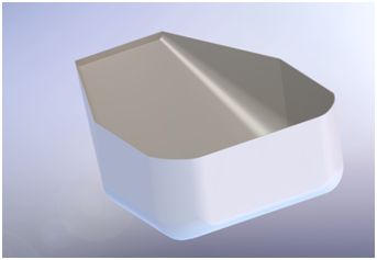
Wedge Fairing
This design is based on the assumption that a relatively small amount of air makes it under the tractor while most of the air is separated by the tractor and flows down the sides until it reaches the trailer. The fairing uses a flat front end because there should be little air reaching this face from under the tractor. Rather, the air flowing along the side of the trailer cannot immediately enter the void under the trailer because it is blocked by the large wedge. When it does enter the under the trailer, it gradually slopes up towards the trailer underbody. This air entering the underbody can then flow out the back and help re-pressurize the low pressure region behind the trailer.
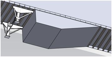
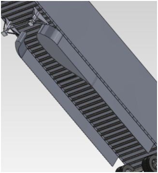
Airfoil Fairing
This fairing uses an airfoil design. It is composed of two separate airfoil type shapes which lead into a skirt which runs most of the length of the trailer. This design takes into account the air flowing under the front of the trailer from under the tractor. Most of this air stream will be pushed towards the exterior of the trailer where it will then be kept outside of the trailer via the integrated side skirts. The small amount of air that is not pushed from under the trailer is allowed to pass between the two airfoil shapes and continue down the center of the trailer. The air flowing down the center of the trailer then contributes some flow to the low pressure drag region behind the trailer.
SolidWorks Results
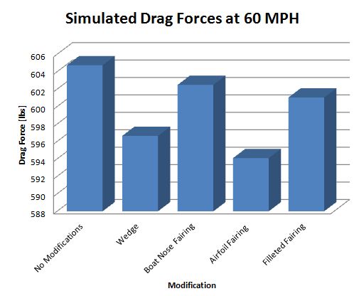
Figure 1- Simulated Drag Reduction
SolidWorks Flow Simulation was used to conduct a computational fluid dynamics (CFD) analysis of various fairing shapes to determine drag forces that may be experienced by a semi trailer. Five design ideas, four of which are shown in Figure 1, were simulated at 60 miles per hour. The resulting drag forces are shown in Figure 1. From our simulations, the Skirt fairing resulted in the highest drag reduction. This reduction in drag is believed to be due to the partial elimination of the low pressure zone beneath the trailer. The models that were simulated incorporate a “moving wall” boundary condition underneath the trailer which represents a moving roadway. The coefficient of drag for the trailer with no modifications was found to be 0.55. The drag coefficient for the trailer with the Skirt attached was found to be 0.54. This represents a 1.8% reduction in the coefficient of drag.

Figure 2- Cut Plot of Velocity
