System Architecture
Intial Hardware
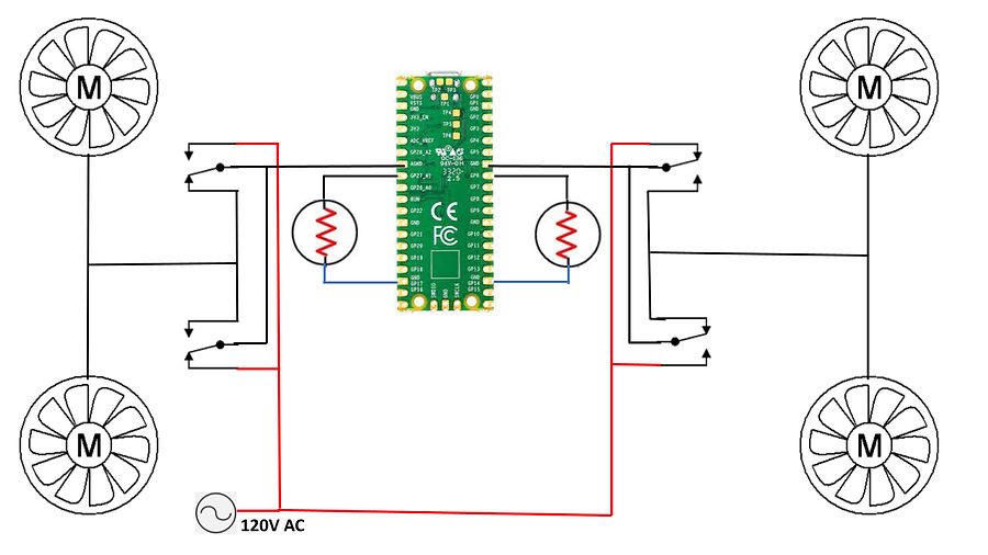
Figure 1: Initial Prototype of System
The architecture of the system design is composed of fans two intakes and two outtakes, two thermistors one outside and the other outside, relays to turn off the fans, a voltage source the solar panel, and a Raspberry Pi controlling the whole system.
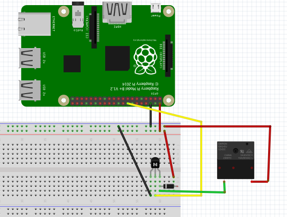
Figure 2: Inital Relay Schematic with Raspberry Pi
With this schematic and code, we are able to get the relay to turn on and turn off and on the fans. The relay, after receiving a signal from the Pi.
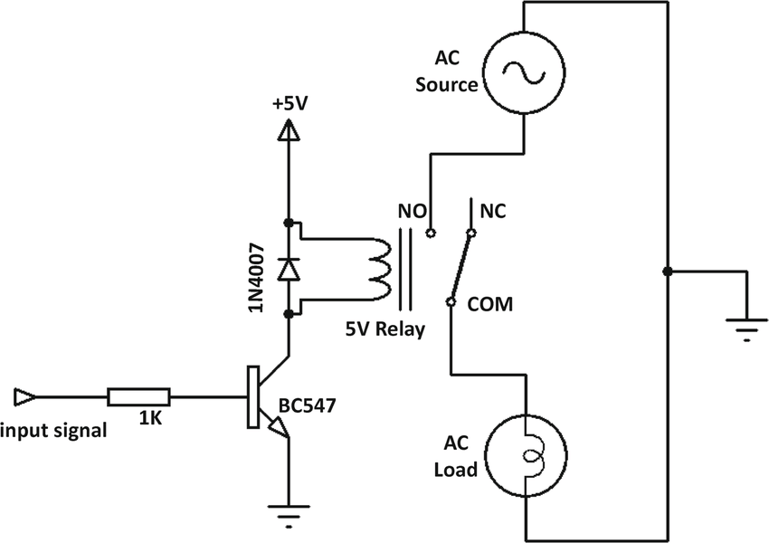
Figure 3: Relay Circuit with AC Supply
Signal relays are a crucial component of our circuit because they help the system open and close the circuits by receiving electrical signals from outside sources. The relays we are using run off of 5 volts. The Pi headers are wired to the relays, and we can use code to transmit a positive or negative signal to switch the fans on or off.
Final Design
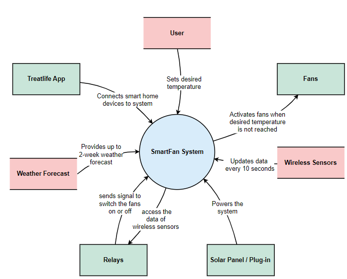
Context diagrams display how a system interacts with other external factors that it is intended to communicate with.
In order to comprehend the environment in which the system will work, diagrams illustrating the system context is helpful.
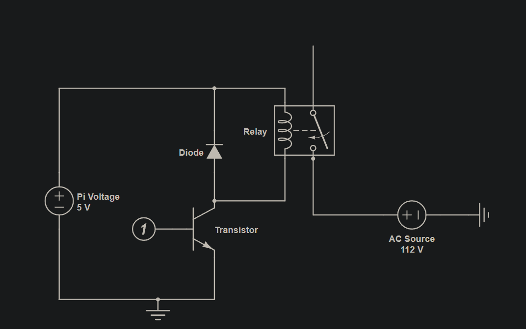
Above is our relay circuit diagram that creates our system. The signal relays are a crucial component to our circuit because they help the system open and close the circuits by receiving electrical signals from outside sources. The relays we are using run off of 5 volts. The Pi headers are wired to the relays, and we can use code to transmit a positive or negative signal to switch the fans on or off.
3D Printed Sensor Shield
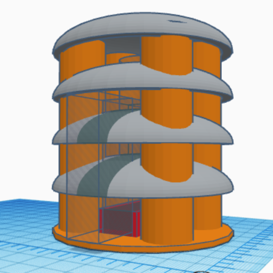
Figure 4: 3D Sensor Shield Design
Following our choice to purchase the window unit, we still wish to include more sustainable design elements. Our sponsor informed us of the Stevenson shield/screen design for our wireless temperature sensors. The Stevenson screen is a meteorological screen to shield instruments against precipitation and direct heat radiation from outside sources, while still allowing air to circulate freely around them.
Hardware
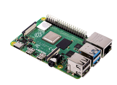
Raspberry Pi
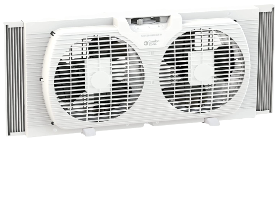
Window Unit Fan
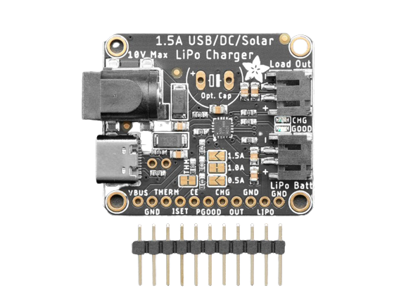
Universal Solar Charger
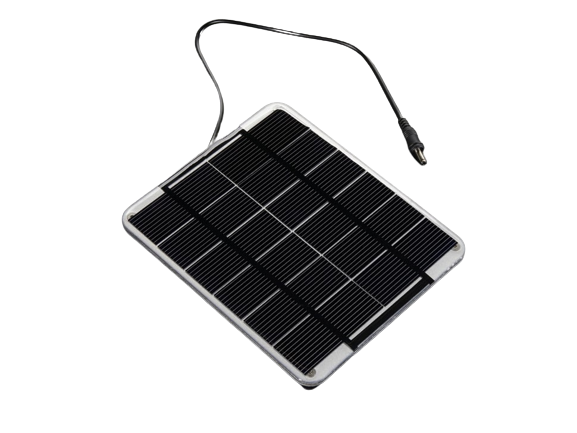
6V 2W Solar panel
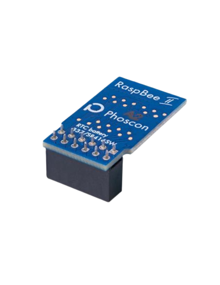
Phoscon Raspbee II
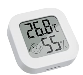
Zigbee Temperature Sensor
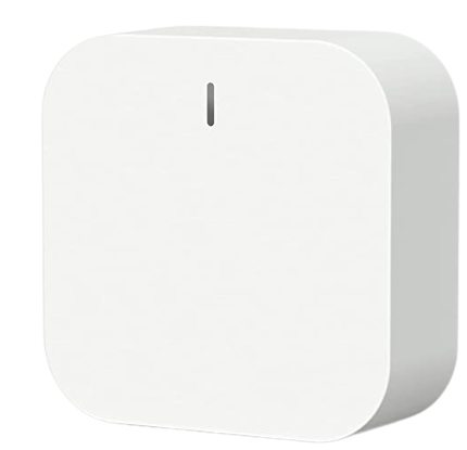
Zigbee Gateway Hub

T81N5D312-24 Signal Relay
Implemented Technologies
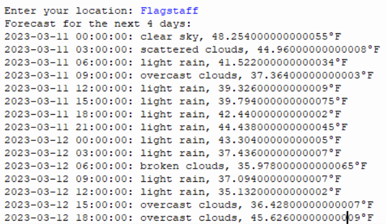
Figure 5: Open access data from AccuWeather
Using available data from websites like AccuWeather, we can predict future loads and operate accordingly (e.g. bring the house colder than desired at night if the next day is expected to be particularly hot).


Figure 6: Predictive Algorithm
Taking into consideration the forecasted temperature, our algorithm will predict the temperature outside for up to a whole day in advance and compare that with the desired indoor temperature. The algorithm considers two scenarios, one where the fans run to cool the house at night in preparation for a hot day, and the other where the fans heat the house during the day for a colder night. These scenarios are implemented when the two temperatures detected by our sensors follow the forecasted temperatures set for that day.
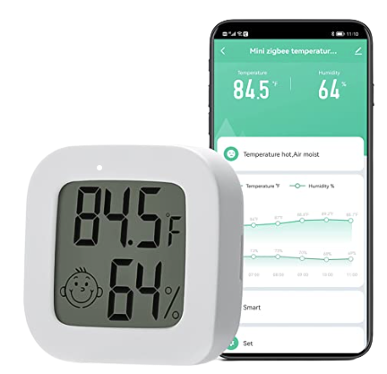
Figure 7: Zigbee temperature sensor & Smart Life app on a mobile device
The Zigbee Gateway Hub component of SmartFan supports a maximum of up to 128 tuya Zigbee smart devices, compatible with Alexa, Google Home Assistant and Apple HomeKit. Customers can instruct their smart thermostat to adjust their home's temperature. The Zigbee wireless sensors record and provide humidity readings in addition to precise temperature readings. The Smart Life app, which is connected to the Zigbee Gateway Hub, allows for remote control of the sensors any time, from any place.
