Electronics
Preamplifier
The team built a transimpedance amplifier which was able to take the tunneling current in the scale of nano Amps to be amplified and outputted as voltage. The preamplifier uses a TL071 op-amp due to its low-noise and low input bias current capabilities. In order to have a gain on the current to voltage, the feedback resistance used was 100MΩ.

Due to the output voltage being negative, an inverter was added to the output of the amplifier to obtain positive voltage output that can be read by the digitally implemented amplifier. From further testing during the integration process, the output current contains high electrical noise which causes the signal to be affected due to the current input being very low.
Piezoelectric Scanner & Tip Placement
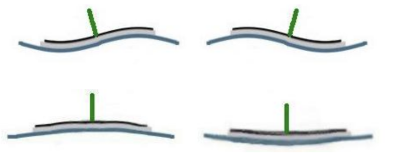
The team also started construction of a high voltage amplifier, but due to long shipping times for SMD component protoboards and delays and campus closures because of snow, we were not able to finish construction of the high voltage amplifier. To prevent falling further behind in our schedule, and with guidance from our client, the team decided to change the piezoelectric driver used to move the scanning tip from a tube scanner to a disk scanner as it can be driven using significantly lower voltages than the tube scanner, with about 0.16 microns of displacement per volt.
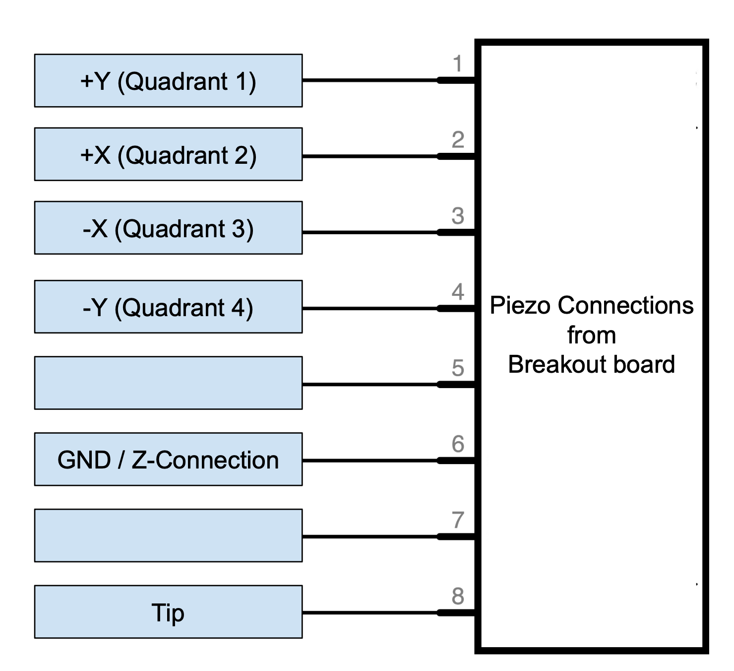
This changed the circuitry for connecting to the driver slightly, but the function and general idea is largely the same; the silver electrode on the top of the disk will be divided into four sections(one for each axis, ±x and ±y) and the back is also connected to ground. Z displacement will be driven by applying an equal voltage across all quadrants of the silver electrode, and lateral(x and y) displacement will be driven by applying a voltage differential between opposing quadrants.

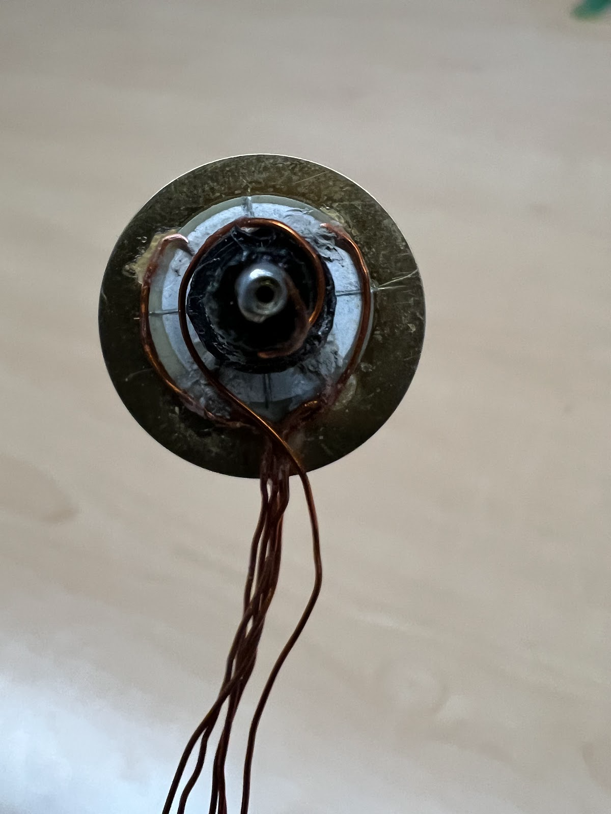
The piezo disk scanner originally only contained one quadrant so to adjust this, the disk’s electrode needed to be divided into four quadrants but scratching it with a precision knife or box cutter. The four quadrants need to be equally divided to ensure the movements of the piezo are equal. To ensure the electrodes are completely separated, an ohm meter was used to test that there were no shorts between the electrodes.
Once this testing process was completed, the connections to the piezo were made with conductive silver paint to avoid damaging the ceramic on the piezo. Additionally, super glue was used to keep the wires in place due to the silver paint not being able to hold on to the wires on its own. In this case, the Z axis was on the stainless steel disk therefore a wire was attached to the back side of the piezo.

To finish this process, the tip holder was added to the center of the disk, over the ceramic. The holder was composed of a leftover peg from the mechanical structure, and a pin from the IC socket was inserted in the center of the peg. When inserting the tungsten tip to this holder, silver paint was used once again to make electrical contact with the wire. Our team found it essential to keep all wires organized which is why they were all soldered onto a PCB protoboard.

