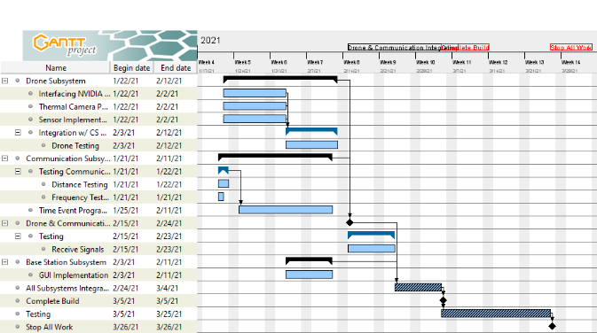
Our gantt chart


In the image above, we have planned out our schedule for the Spring Semester using GanttProject Software. We have divided the the project into three major task, of which are each of the subsystems we have defined in our project: drone, communication, and base station subsystems. Within each of those major tasks, we have also assigned subtasks to be done which consist of testing, programming integration, and others. Once each of those major tasks have been completed, we first will be interfacing the drone system with the communication system to ensure that we are able to send information from the drone computer to a test computer. With that completed, we move towards interfacing the base station subsystem to the rest of the system testing that the GUI functions are working properly. Our hope is to follow this scheduling to turn up a successful project at the end of the semester.

Current Project Design Progress

At the end of the project, our design team was able to complete all the tasks outlined on the Gantt chart except for the implementation of the GPS sensor. We experience difficulties interfacing the sensor with the UART serial
communication of the Nvidia Jetson Nano. Throughout this experience, we gained experience working the Nvidia Jetson Nano microcomputer, its GPIO pins and CSI port. We were able to work with the High Definition and thermal cameras, sensors, and Software Defined Radio. We gained skills programming in python, learned to work within our team and an interdisciplinary team, improved our critical thinking and problem solving.

Plans for Testing

Unit Step-by-Step Test
Test Name: CS Algorithm Integration
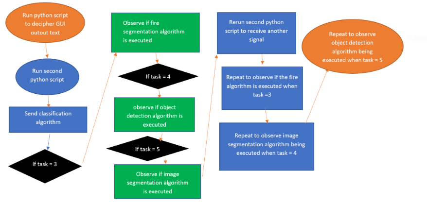
Description: Algorithms developed by the CS team have been listed as tasks for the drone to execute based on an output text of the GUI. The tasks defined by the CS Algorithms will be Fire Classification, Fire Segmentation, and Object Detection. In this test we will be seeing if the GUI correctly outputs a text file with tasks depending on the user and see if the CS algorithms will be executed by output of the display on the GUI.
Graphic:


Unit Step-by-Step Test
Test Name: GUI Interaction
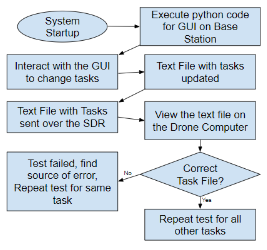
Description: The data feed generated at the drone system will be provided to the user using a User Interface. The user will be able to access sensor data, GPS information and images from the camera feed. This test will be conducted to ensure that the user is able to access these data through the GUI.
Graphic:


Integration Test
Test Name: Subsystem Integration Testing
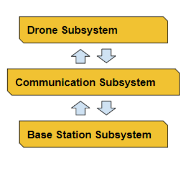
Description: During this test, our design team is testing the integration of all subsystems to ensure that the communication, drone and base station systems are in constant communication. In the communication subsystem the software defined radio hardware should be able to transmit and receive sensor data, images, text and GPS signals across the drone and base station subsystem.
Graphic:


Unit Matrix Test
Test Name: Autonomous System Operation
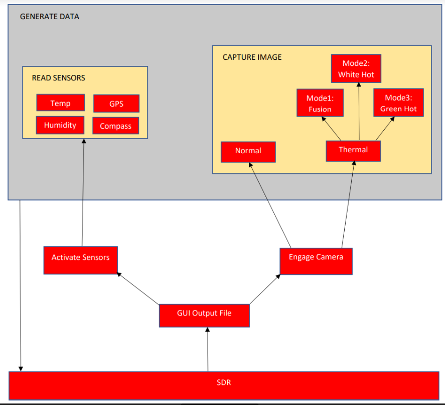
Description: This test will be conducted to determine the autonomy of the system. Determine if the cameras will capture accordingly, the viewing modes will change off of input, the sensors will begin reading values, and signals between the drone and base station will occur on command.
Graphic: