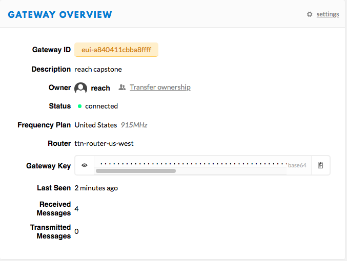
Our design utilizes an ESP32 which can be directly connected to our LoRa node. The ESP32 can connect to an end device easily via bluetooth or wifi. If the end device follows the same wifi protocol as the ESP32 connection can occur easily. The plug and play aspect is important because it means that a device will be able to easily connect and that whenever there is data to be sent the network will be ready to handle it. The team also reduced the power consumption of the arduino so that it would have a better chance of reaching the 6-month goal. Another aspect of our project was the type of data that would need to be collected. Since our dragino gateway is a class A gateway it utilizes ALOHA protocol. This means that it is well suited for event driven data collection. Event driven data collection is also preferred for this project because it will require much less power than continuous data collection would use. There is a lot of variability to how long the node could be powered because it would depend on how often the event driven data collection occurred. Our client also requested that we use the things network (TTN) as the server for this project. This means that our gateway is registered to the TTN. The gateway can be configured in multiple ways which can be beneficial to the user. There are also many LoRa settings that need to be configured so that the LoRa network can be completed. With all of these components working together and communicating a complete LoRa network can be formed. The subsystems that the Reach team deemed necessary are key in ensuring that the project is successful and when they are all working together properly an effective plug and play LoRa network will be created. This network will help to collect data that can be analyzed for a variety of applications.
The gateway would simply need to be plugged in to a power outlet using a 12V barrel plug and connected to the WAN through an ethernet cable. To turn on the LoRa node, a pair of fully-charged 18650 size lithium ion batteries (preferred rating: 3.7 V, 3000 mAh) can first be inserted into the battery enclosure, if simply testing a sensor with a computer, the usb plug can be used to power the node instead.
The operations of the node are performed by a program which would be already uploaded to the devices including a predetermined communication interval; for example, the node could be programmed to transmit data every Tuesday and Thursday of the week. This part of the code in the project was not fully complete but other codes developed up to this point will be available through the team’s Github
The final product developed by the team was a registered gateway and node prototype without any enclosure developed. The node prototype is shown in figure 6 configured using SPI connections between devices. There was additional code created as well for the sleep timer and data transmission from the ESP32 and through the Arduino Uno which would then be encoded and modulated via the transceiver. Along with this, a schematic and PCB design layout was conceived using KiCad software. The files for this will be accessible via Github with the program codes as well. Very little testing was done to work out all possible issues with our LoRa network or with the PCB layout and should be tested and expanded on further.
Moving forward with this project team Reach suggests that more testing be done in order to obtain more accurate numbers for the power usage, communication range, and test for environmental variables. We would also like to see future work include extending the network. Our basic network includes one node and one gateway. The network can be expanded by including multiple nodes and gateways. This means that more data could be collected and the network could span a larger distance. This would mean that our network could be used for even more applications in the future.


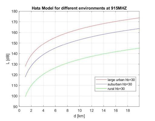
A propagation model was created based on the COST HATA model shown in figure 4. We added the minimum heights of the LoRa node and the gateway and were able to calculate some ranges. We calculated the ranges of different environments, a rural, urban, and suburban area. According to our model there is about a 8-20 km range depending on which environment it is located in.
Finally, the last task for the gateway subsystem was to do testing. Unfortunately, due to all courses being moved online we were unable to complete this task. We wanted to test to see how different environments or terrains impacted the network. We also wanted to be able to give estimates of how well the network would be able to perform under certain conditions and what the maximum distance that data could be transmitted was.
The gateway was registered and multiple configurations were used depending on where the gateway was being set up. The WAN port suited our needs perfectly when working from home but the wifi client configuration was needed to ensure the gateway would work in the SICCs building. We were able to obtain some basic communication as well. The only place that the gateway fell short was on testing. The gateway subsystem proved to be successful and was a key portion of our final product.