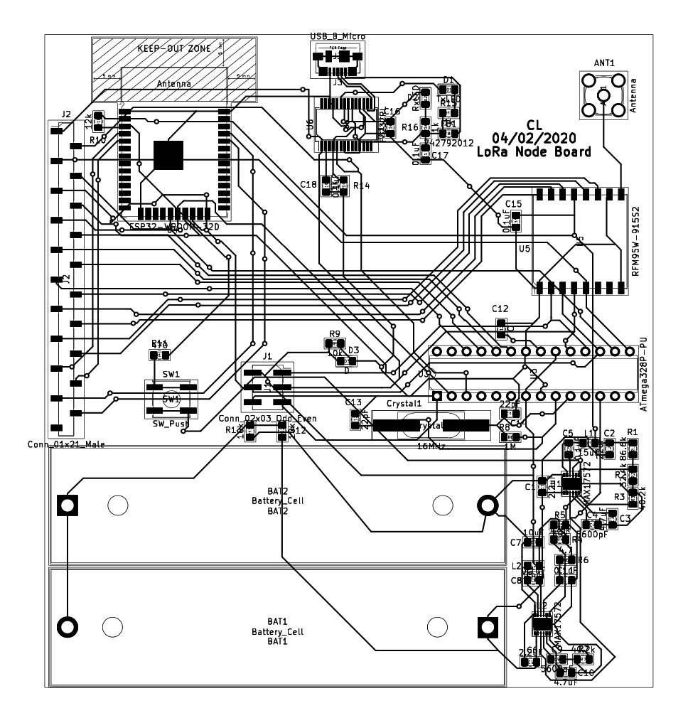


The primary constraints identified in Crowdsensing LoRa is power consumption and bandwidth. Normally, a LoRa node that is paired with a microcontroller, could last over a year on batteries without charge. However, one of the aspects of our node that increases connectivity and user friendliness is the use of an ESP32 and the ESP32’s Wi-Fi capabilities. Bandwidth is extremely low with a LoRa node, this means data needs to be sent in small payloads and sent in binary because the narrow bandwidth isn’t enough to send a large amount of data. This makes the technology difficult for anything requiring a lot of data transmission and more ideal for applications over longer distances where data is recorded and transmitted in some recurring period of time and then places the device in a sleep mode until the next time data transmission is required. The previously described tradeoff is moving less data for longer range and lower power consumption.
Another constraint which was to be expected once our team began testing of our LoRa network, is the obvious forestry environment of flagstaff which is expected to contribute a considerable decrease in range capabilities in the region and may need to be expanded on further in other environments. This is simply a constraint to be prepared for and it is expected that this environmental interference can be counteracted with more power being used to send a stronger signal.
The LoRa crowdsensing project was focused on the node device and the end-to-end communications between an end-device and the things network server. Our team focused on these three main subsystems: the gateway, the node, and the power supply. The gateway is the device which connects the entire LoRa system to the internet and with that, the things network. The node is what connects to the gateway using RF communications and also exchanges data from the end-devices through Wi-Fi. The application in our project intends for the node to be battery powered for as long as possible, 6 months being the goal. We focused on the power supply by attempting to maximize power efficiency, reduce power consumption, and choose the most ideal battery to use.
The project design process began by configuring the gateway and preparing a node which we could send data with to the TTN server. With the gateway working, we would be able to test the node and optimize it by configuring a sleep timer and using code libraries to exchange data between the node components. Still using power provided through a usb, the various functions and modes would be operated and measured to find the amount of power being consumed during transmission, reception, and sleep modes. This would then begin the optimization of the power supply and power consumption of the node. Options such as solar panel use, PCB designing, and choosing the number of batteries would be considered and evaluated. The design process begins with the LG01-P dragino gateway, and the remaining subsystems would be built upon that, however the node prototype is where actual measurements of power consumption and data throughput to the TTN occurred. A requirement of our project was also enabling our node to be user friendly and available for use when using nearly any end-device without the user needing additional reconfiguration of that device. Enabling the described user-friendly end-to-end communication was the primary objective of our node.
From these tests we found the optimal number of batteries, the class of choice for the LoRa Media Access Control (MAC) protocol, and a few possible directions of increased power availability. We could see from the TTN the messages being sent from our end-device and the next step would be taking the device into the field and begin testing the range able to be acquired from our node in a given environment such as Flagstaff, added that some form of protection is applied to the node device.
Operations
- Research of LoRa and Remote Sensing
-
Defining project requirements
- Wifi capability
- Plug and Play
- Node being powered for as long as possible
- Taling to professor about power consumption
- Talked to Razi about propagation modeling
- Meet with graduate student, Robin, about gateway configuration
Key Milestones
- Calculations of Power Supply
- Connecting the Gateway to the Server
- Sending data to the Gateway from the Node
-
Outputs:
Hardware
- Dragino Gateway
- Dragino Shield
- Arduino Uno
- Arduino Mega
- ESP32
Decisions and Tradeoffs
-
Decision to Use Uno
- Made this decision to reduce power consumption
- Continuous remote sensing vs event driven remote Sensing
- Latency
-
Plug and Play capabilities are more important feature
- This may compromise the power supply
Software Tools
-
Visual Studio Code
- For coding the website
-
Arudino IDE
- Used to program LoRa Node
- Used to program LoRa Gateway
-
KiCad E.D.E
- Used to make the schematics
-
Matlab
- Used for propagation model of LoRa Node
Simulation
-
Propagation Model for LoRa Node using HATA
- Calculation for Urban Area
- Calculation for Suburban Area
- Calculation for Rural Area