System Description
The BabyLift will incorporate rehabilitative therapies into everyday activities. The main design components are; frame to carry the load, weight scale to weigh the participant, participant repositioning pulley system and set of sensors and 3 microprocessors to read and store data. Two peripherals, joystick and a smart watch will control the car.
The Baby Lift
The participant will control the BabyLift when the system is activated. The BabyLift is controlled by 2 switches and both need to be “ON” at the same time to activate the BabyLift. The weigh scales is one of the switches (S1). The participant’s caregiver or guardians and physical therapists will need to determine the “trigger weight” (TW), this will vary depending on the age, weight and ability of the participant. When a weight greater than the TW is registered on the scales, switch S1 is activated. To find the best value for TW the team recommends starting at 25% of the participant’s weight and using a trial and error process to refine. Initial the TW is controlled by a 10 input rotary switch. The second switch (S2) is activated by pressing the select button on the joystick. The button will be disabled until all actions are completed.
Wheatstone bridge
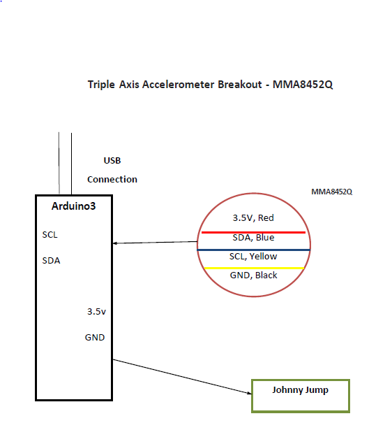
The team will use a load sensor combinatory board that was created to combine the 12 wires found in a bathroom scale into the standard 4-wire Wheatstone bridge configuration. The 4 output wires from the combinatory are connected to the amplifier

Harness
The team will use the harness of a Johnny Jumper to lift and lower the participant. The Johnny jumper’s supporting brace will be modified to suit its new function. One of the projects goals is to make the BabyLift compact. The Johnny jumper’s brace houses the spring and gives the Johnny Jumper strength and springiness. The team will relocate the spring to a point closer to the actuator.
Joystick
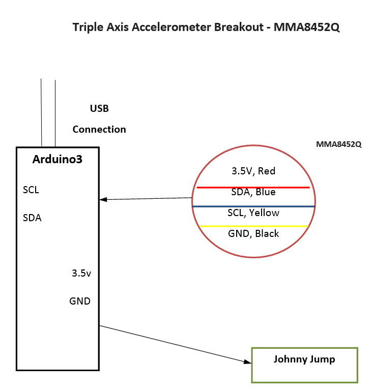
The primary user interface is the joystick. It will be fastened to the steel pipe at the front of the car. It will be attached to the car in such a way that allows the participant to move freely from a sitting to standing position. It will control the cars directional movement and the select button will control the lift. The team will use the 2 motors from the original design.
Software
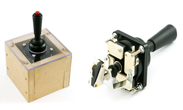
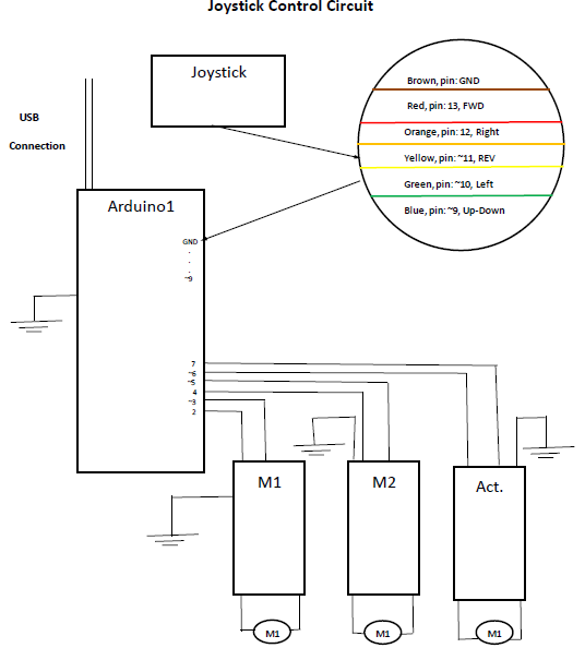
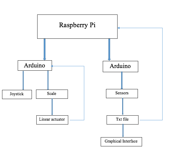
The following is the BabyLift system software flow chart. The raspberry pi will be the brain of the system and store Arduino’s collected data. The system will use 3 Arduino’s to control and read data. One Arduino will control both motors and the other will control the linear actuators. The third will control the cars sensors.
Linear Actuator
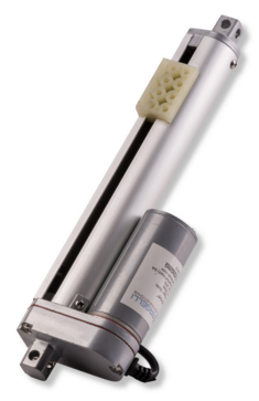
The team purchased a 12V DC linear actuator in this design. It will lift the participant in a vertical plane a maximum of 10 inch vertically in 3 to 6 seconds. The car’s base of the car will be reinforced to secure the actuator.
The team build a linear actuator prototype to aid in the decision making process. Yet, the linear actuator the team build was too slow to do its tasks. The team decided to buy a new linear actuator
Last Updated: 4/25/16