Final Products
Our team's final product consist of 3 main parts: the potentiostat circuitry, micro-controller to GUI communication, and housing. The bulk of the team's hours were put into improving the micro-controller to GUI communication.
Potentiostat Circuitry

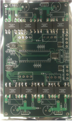
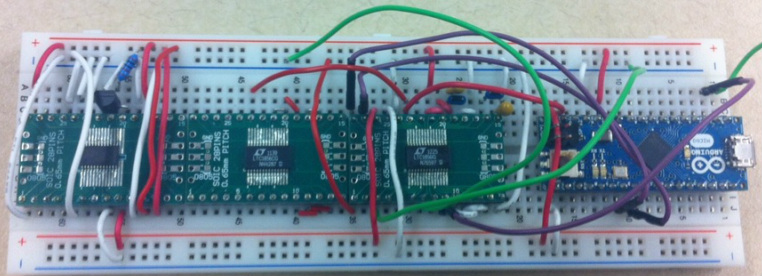
Located below is a breadboard version of the potentiostat circuitry. To the right is the PCB version that ARBsource had made from this design. This current prototype has 2 working ADC's which can read two different channels of data at a time. The Arduino Nano shown here is our micro-controller. This micro-controller controls the ADC and DAC per channel and establishes a solid communication with the user's computer by talking through the GUI.
GUI

The GUI receives the data from the micro-controller and proceeds to graph and log this data. Currently the highest sample rate we have been able to achieve is a sample every .01 seconds. This resolution exceeds the needs of ARBsource in their sampling rate. Some of the features of this GUI are:
Shown to the left is a sample that was taken for a duration of 12 hours. This shows that this system can run for long periods of time without crashing.
- Changing the sample rate
- Graph voltages of reference, sensing, and counter electrodes. It also has cyclic sampling capabilities.
- Change the duration of the graph
- Change the working electrode potential in respect to the reference voltage.
Shown to the left is a sample that was taken for a duration of 12 hours. This shows that this system can run for long periods of time without crashing.
Housing
ARBsource had our team do research on what they should be looking for in housing the power-supply, PCB, and micro-controller. Since having a working ESD safe housing is a year or two down the road for them, they did not require us to have a physical prototype of the housing. After research, we advised ARBsource that having a solid metal connector for the different channels and USB connection would be better for their certifications that they will need later on. The housing will be a semi-completely closed environment. The only opening in the housing will be for the fan to cool down the power supplies. The housing would be latched shut and since the channel and USB connections are made outside of the housing, opening the housing will only occur on rare occasions of part maintenance. All parts in the housing would be securely mounted to prevent damage to the sensitive electronics inside.
Last Updated 4/20/2013
