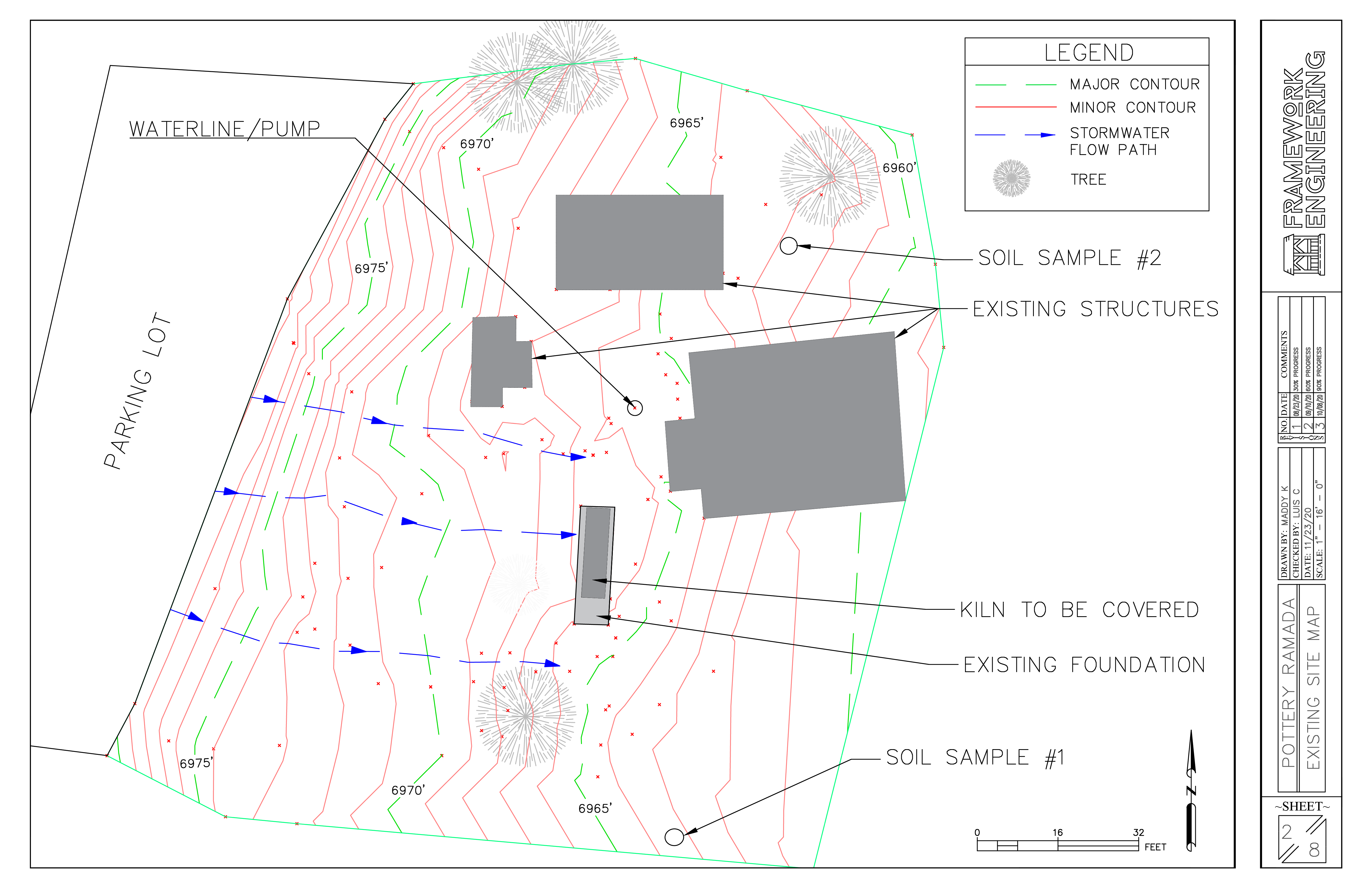
Our team surveyed 120 points throughout the project site and used that data to create the topographic map seen below. Existing structures and the natural stormwater drainage paths were drawn in to create a site map.
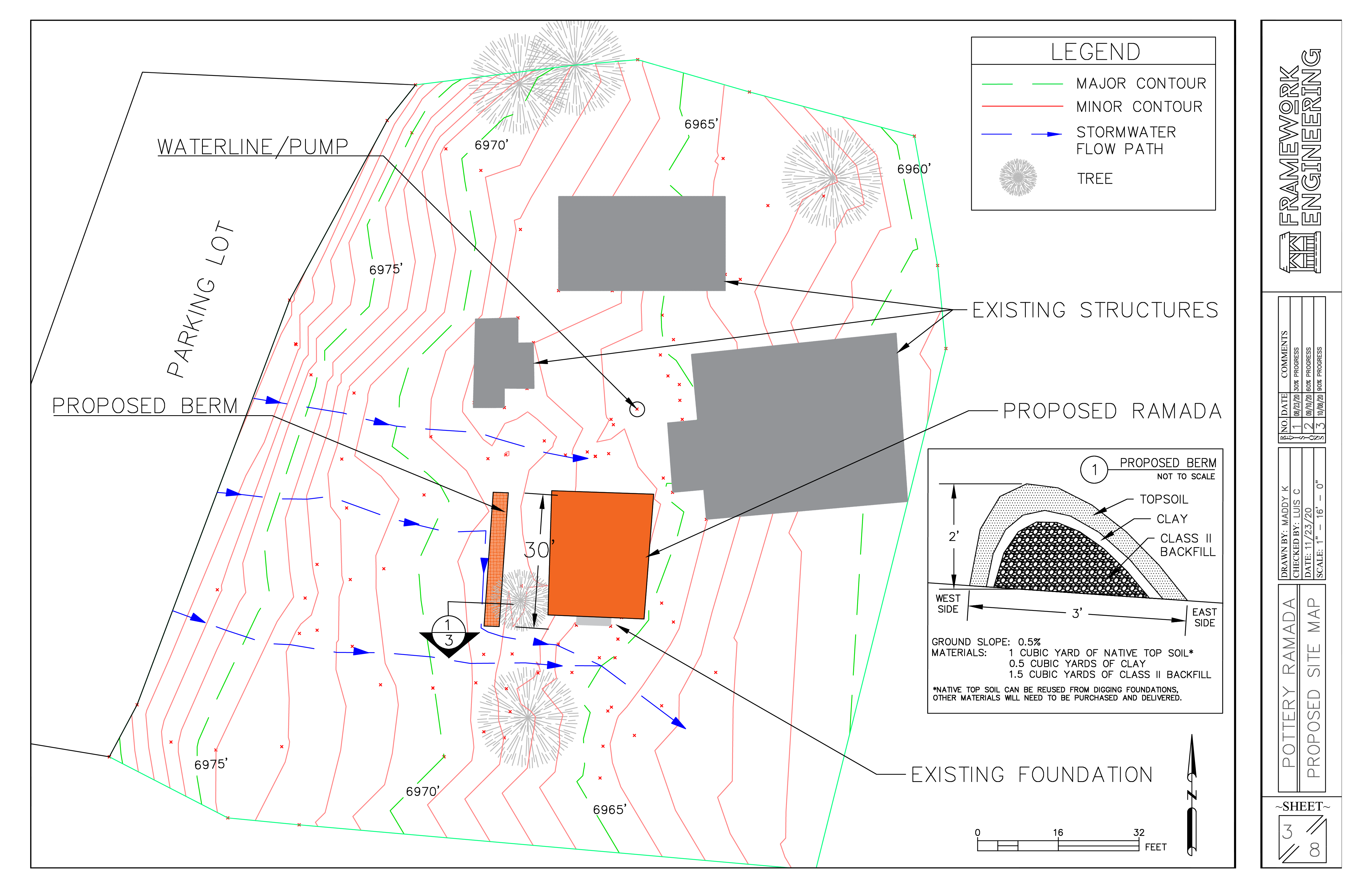
After analzying the existing site map, it was determined that we needed to find a solution to prevent future flooding near the kiln and proposed ramada. We proposed building a berm 15 feet away from the west edge of the kiln that will re-direct stormwater around the kiln. The berm is designed to be 3 feet wide, 2 feet tall, and 30 feet long. Further details can be seen below.
Before we could start our design, we first had to decide whether we wanted the roof to be designed as a monoslope or as a pitched roof. To determine this, we used a decision matrix with seven different criteria. After tallying up the scores, it was determined that we would design the roof to be monosloped.
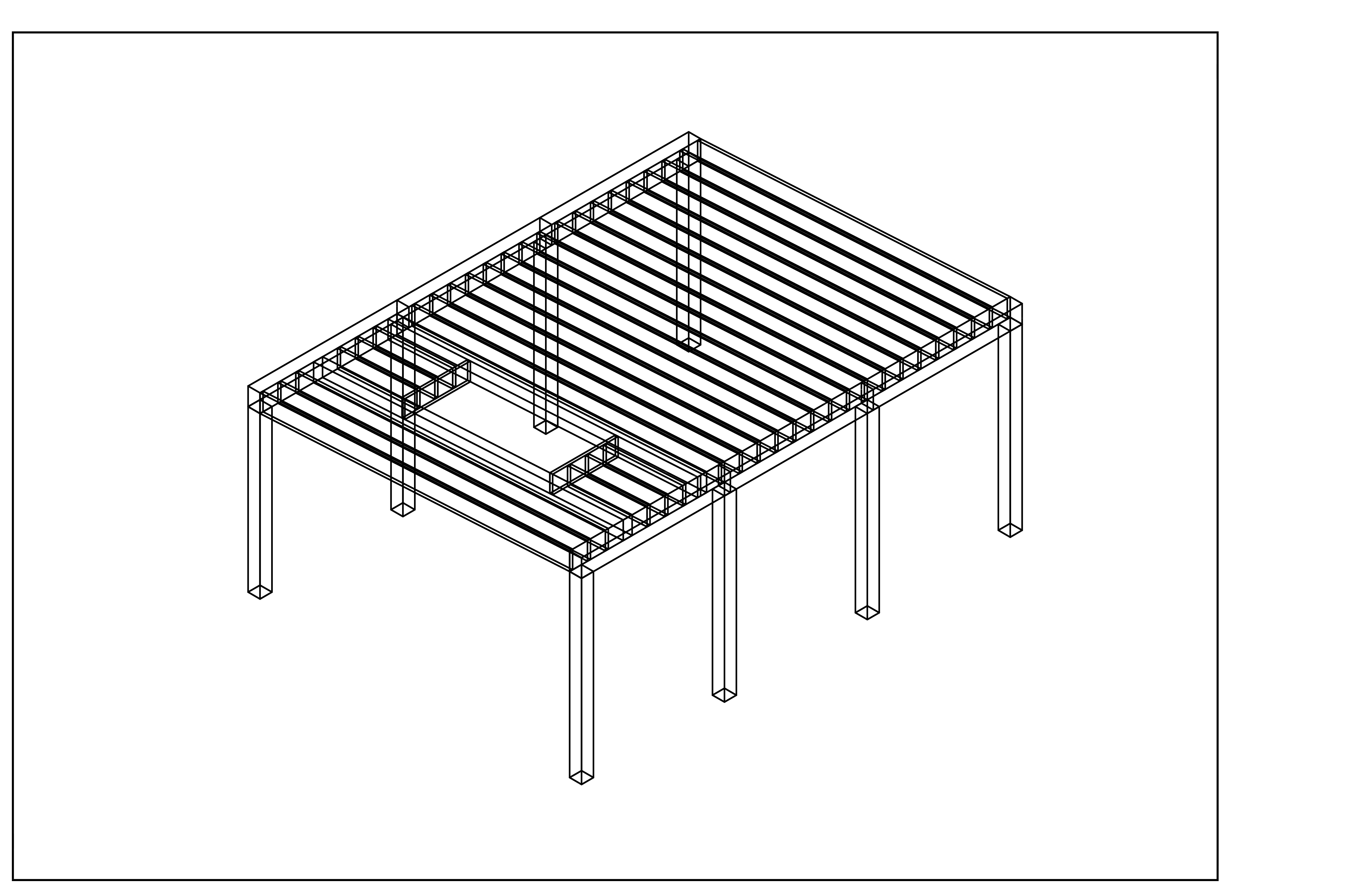
After determining our design loads based on the International Building Code, American Society of Civil Engineers (ASCE) 7-16, The City of Flagstaff Standards, and NAU Technical Standards, we were able to design our ramada. It was determined that the ramada would be rectangular in shape with a width of 18 feet, a length of 24 feet, and a roof slope of 1:18. The slope of the roof depended heavily on ensuring that the chimney protruded enough through the roof to prevent any possible cases of the roof catching on fire. Therefore, the height of the columns governed the slope of the roof. The height of the east columns will be 10 feet tall and the height of the west columns will be 9 feet tall to ensure appropriate clearance. A figure of the ramada's overall geometry can be seen below.
Wood members were selected based on size and availability. The joists are 2x12 Hem Fir No. 2, the beams are 8x12 Douglas Fir No. 2, the columns are 8x8 Douglas Fir No.2, and the joists adjacent to the chimney opening are (3) 2x12 Hem Fir No. 2 wood members nailed together. Further details can be seen in our Plan Set.
A figure of our roofing plan can be seen below. The figure illustrates 15/32" plywood (structural member) spanning perpendicularly over the joists with corrugated metal (non-structural member) nailed on top of the plywood. The corrugated metal roofing spans parallel to the roof's slope.
Joist to Beam Connection: HU212 and HU212-3 (for joists adjacent to chimney opening)
Beam to Column Connections:
Middle Columns - 1616HT
End Columns - LCE4
Column to Foundation Connection: MPB88Z
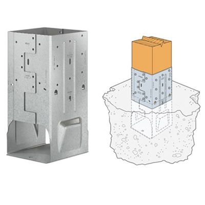
For our foundation design, we decided to use square foundations using Terzaghi's Bearing Capacity equation. It was determined that our foundations would be 2 ft by 2 ft piers made of 4000 psi concrete. The piers reach a depth of 2.5 ft below the surface with 6 inches above the surface to prevent the wood columns from weathering. The following images show the technical details for our piers. Further calculations and descriptions of our reinforccan be seen in our Final Report and Plan Set.
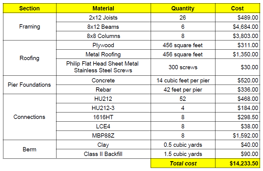
Our final cost estimate for the materials needed can be seen in the table below. Our original budget was around $10,000. We believe the costs could be reduced since our prices were found on retail sites and not on commercial sites. It is also important to note that at the time of producing this cost estimate, lumber prices were increased by around 60% due to the COVID-19 pandemic and the resulting economy.
