Fuselage Design
The fuselage was chosen to be a 20 inch long, carbon fiber hollow tube, with a diameter of 4" ID. This was selected as it provides enough space to encapsulate the payload container along with all electronics needed.
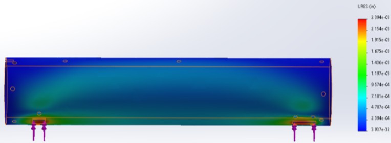
Fuselage Deflection
This figure illustrates the deflection of the main fuselage under a 250lb load applied to each landing gear connection (front and back). The maximum deflection can be seen as .0024 inches. With the material being set at carbon fiber (what the team plans on using in the final design) we shouldn't need to worry about any sort of cracking or complete failure.
Tail Wing Design
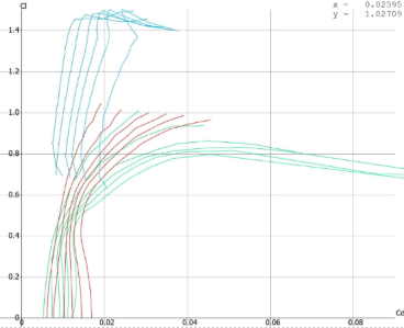
Coefficient of Lift vs. Coefficient of Drag
Shows the relation between the coefficient of lift to the coefficient of drag at the angles of attack. The symmetric airfoils, 0009, and the 0012 display very similar results which only start to fluctuate at the larger angles of attack. The NACA airfoil 6409 has a camber which means it will generate higher lift at all angles of attack without producing much drag.
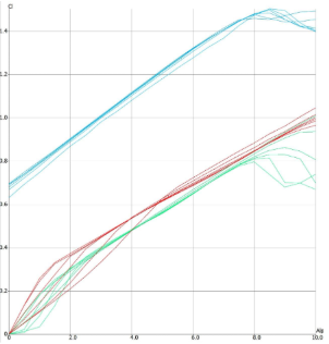
Coefficient of Lift Across Increasing Angles of Atack
Shows a similar trend as observed above with the fact that the cambered airfoil once again starts to produce higher lift coefficients all the way through. The worrying part about the NACA 6409 (Blue lines) and NACA 0009 (Green lines) is that at the higher angles of attack the graphs being to deviate from the linear path, which indicate signs of stalling. If we can limit the point at which stalling occurs this will allow to have a much more stable flight without the risk of crashing as easy.

Pitching Moment Across Increasing Angles of Attack
The last area of useful information for the tail-wing is the pitching moment. After doing some research on how the pitching moment should act for the tail, it was found that symmetrical ones work the best. If the tail wing is also producing a negative pitching moment it means the main wing must be able to produce excess lift to keep the aircraft level. With much larger planes this is not really a problem but because handling and stability are more sensitive for RC aircraft this would create issues. So, reducing the negative pitching moment will give more control and stability in the air.
Main Wing Design

Local Lift
The local lift graph shows a maximum coefficient of lift to be around 0.8, and slowly decreasing as the wingspan increases in length, which is normal for aircraft wings. This is a slightly less value than our calculated coefficients of lift, however, the team is still moving forward with this wing design as our flight testing data shows that we can take off without any elevator control.

Local Drag
The local drag graph shows an interesting plot, with a constant root coefficient of drag at 0.05, with a drop off to 0.038 and constant increase to 0.075 at the wing tips. To combat this high coefficient of drag at the wing tips, the team designed Hoerner-like end caps to gradually reduce surface area at the wingtips, thus decreasing our drag.
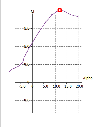
2D Coefficient of Lift vs. Alpha
The team ran a batch analysis in XFLR5 at Reynold's numbers of 100,000-400,000. This graph shows the behavior at 300,000 Re. We can see a maximum Cl at around a 12 degree angle of attack (Alpha). This can be taken as a high estimate, as it is only 2D behavior, and the software makes common experimental assumptions.
3D Coefficient of Lift vs. Alpha
3D Coefficient of Lift vs. Alpha While the software can produce solutions at high angle of attack, this AoA (>15 degrees) is typically beyond stall for many airfoils at the Reynolds numbers of interest, where flow becomes massively separated and unsteady. XFOIL and VLM/panel approaches are primarily suited to attached or mildly separated flow; thus, results at 15 degrees and beyond should be interpreted qualitatively and should not be used as definitive performance predictions without validation. Therefore, we can use our 2D simulation data to approximate our stall AOA to be around 10-13 degrees.
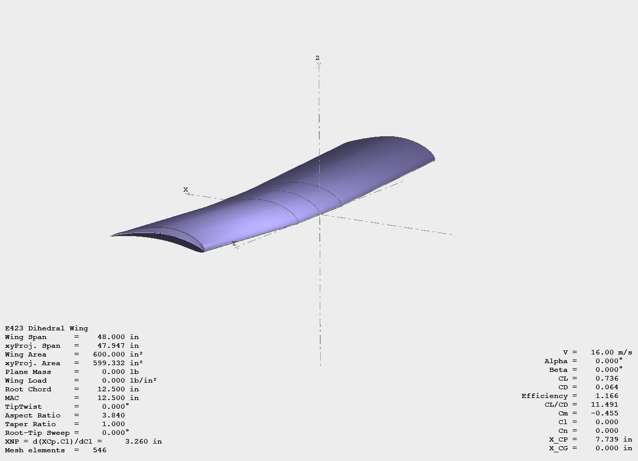
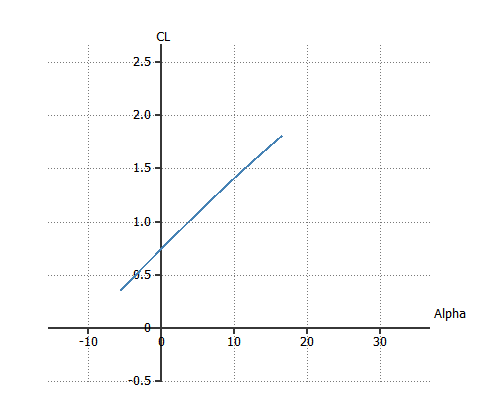
3D Design of Wing Shape
After changing our wing design the E423 airfoil with a 3 degree dihedral shape, the team constructed a 3D analysis of Cl vs. Alpha using XFLR5. This graph give us a better depiction of how our full wing will behave at 16 m/s at a Reynold’s number of 300,000. The main goal of this simulation is to find an angle of attack at which our wing will see stalling behavior, as well as finding a Local Lift and Local Drag graph to confirm our calculations.
Landing Gear Design
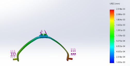
FEA Deflection
This is an FEA analysis of the rear landing gear we intend to purchase. The loads applied are 100 lbs at each axle and 100 lbs applied vertically down at the top of the landing gear where it would be fastened to the main fuselage body. This is a deflection analysis. The color bar on the right denotes the units are mm. While the red areas of the analysis might seem ready to fail, the color bar clearly denotes that the maximum deflection is 0.002318 mm. Thus concluding this is a stout landing gear and has a high factor of safety assuming the forces applied will not be seen.
Electronics / Propulsion
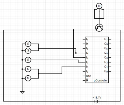
Wiring Diagram
This figure illustrates how all 5 servos (elevator, rudder, 2x aileron, and nose gear) are wired to the battery and servo. With this, the 450W required power limiter is also shown wired to the motor to limit our propolsion.
Center of Gravity
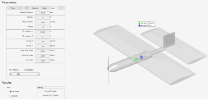
CG Limits
● Neutral Point 0.45*12.5=5.625" from leading edge -Aircraft Intuitive Design Tool
● Neutral Point =5.625+8 = 13.625 in from nose
● Distance from leading edge to CG= 12.5*0.25=3.125"
● Distance from Nose cone to leading edge= 15"
Dependent Dimensions Calculator
Aircraft Dimensioning
● The following calculator finds all vital dimensions to ensure Center of Gravity & Flight Stability
●Open the Aircraft Dimension Calculator