NAU 2022/2023 NASA Student Launch Proposal

.png)
NASA Student Launch Competition
Design Process

As dictated by NASA, the NAU Rocket Club and the Capstone Team were required to contribute to the creation of the Student Launch Proposal document, which was delivered to NASA on September 10th, 2022. The Capstone Team, who were in charge of designing the rocket's payload systems, had to provide an initial outline of what kind of design they were likely to continue to develop. This design outline can be seen below:
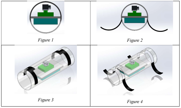
These figures outlined how the design would utilize some form of self-correcting mechanism to ensure that the payload and/or the camera would be able to rotate normal to the ground, as outlined within NASA's PayLoad Requirements (see the Project Overview page).
These figures did not go into any specific detail regarding how the design is supposed to work, as these areas would be covered while the Capstone team conducted their Concept Generation and Selection.
Due to the scheduled dates for various NASA Student Launch deliverables, the Capstone Team's contributions to this document became the team's first step in the design process. This deliverable was due about a week after the Capstone Team had officially been formed.
The team generated 14 concept variants (CVs) in order to generate a set of potential methods for overcoming the various challenges that the payload system would be required to complete. These designs are available within the gallery (right) along with a brief description of what the proposed designs were intended to do.
The team wanted a healthy mix of passive and active methods in which these designs would utilize in order to rotate the camera system normal to the ground plane. As such, a handful of unorthodox methods were also included within these designs in order to allow the team's mechanical engineers to become aware of alternate methods of vertical alignment.
How these CVs were evaluated and narrowed down into the team's final design can be viewed within the "Concept Evaluation" section (below).
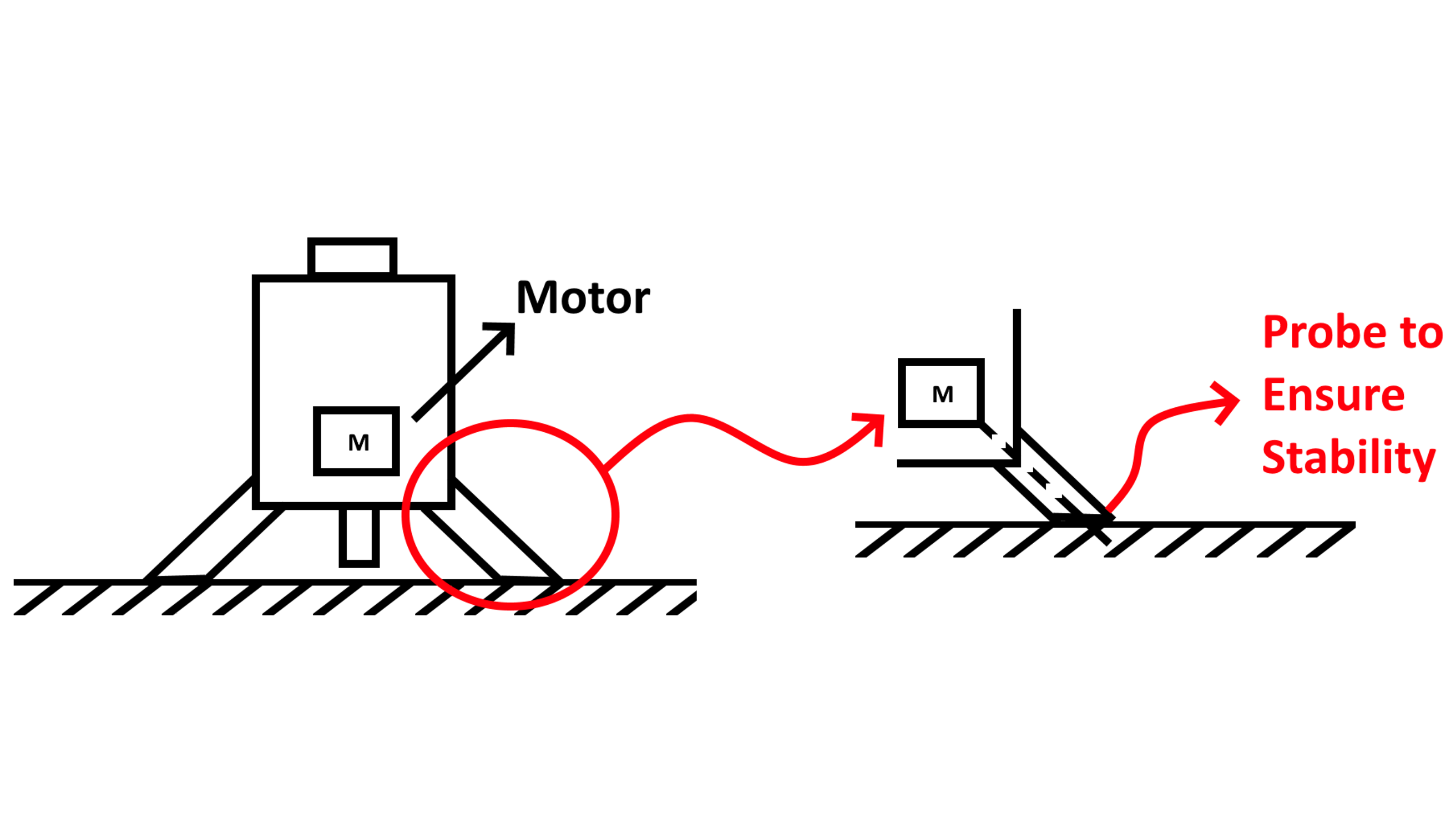
This design utilizes a motorized leg system to flip the design over just enough for the center of mass to begin rotating the entire system on its own.
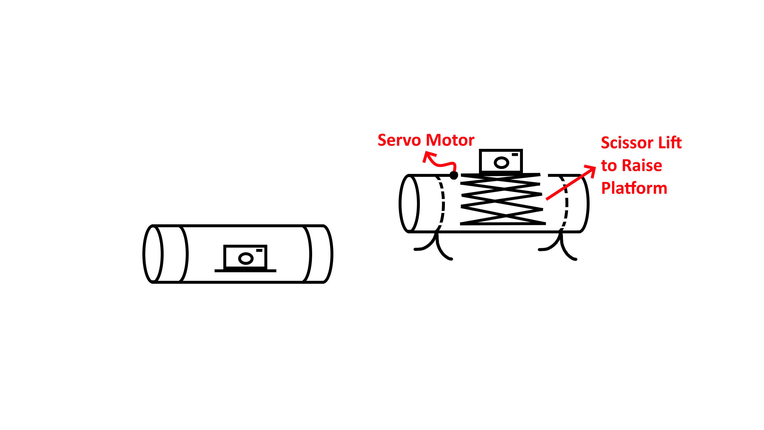
This designs utilizes a set of cylindrical legs to rotate itself normal to the ground. It then uses a scaffolding design to elevate the camera upwards and above any obstacles present on the local terrain.
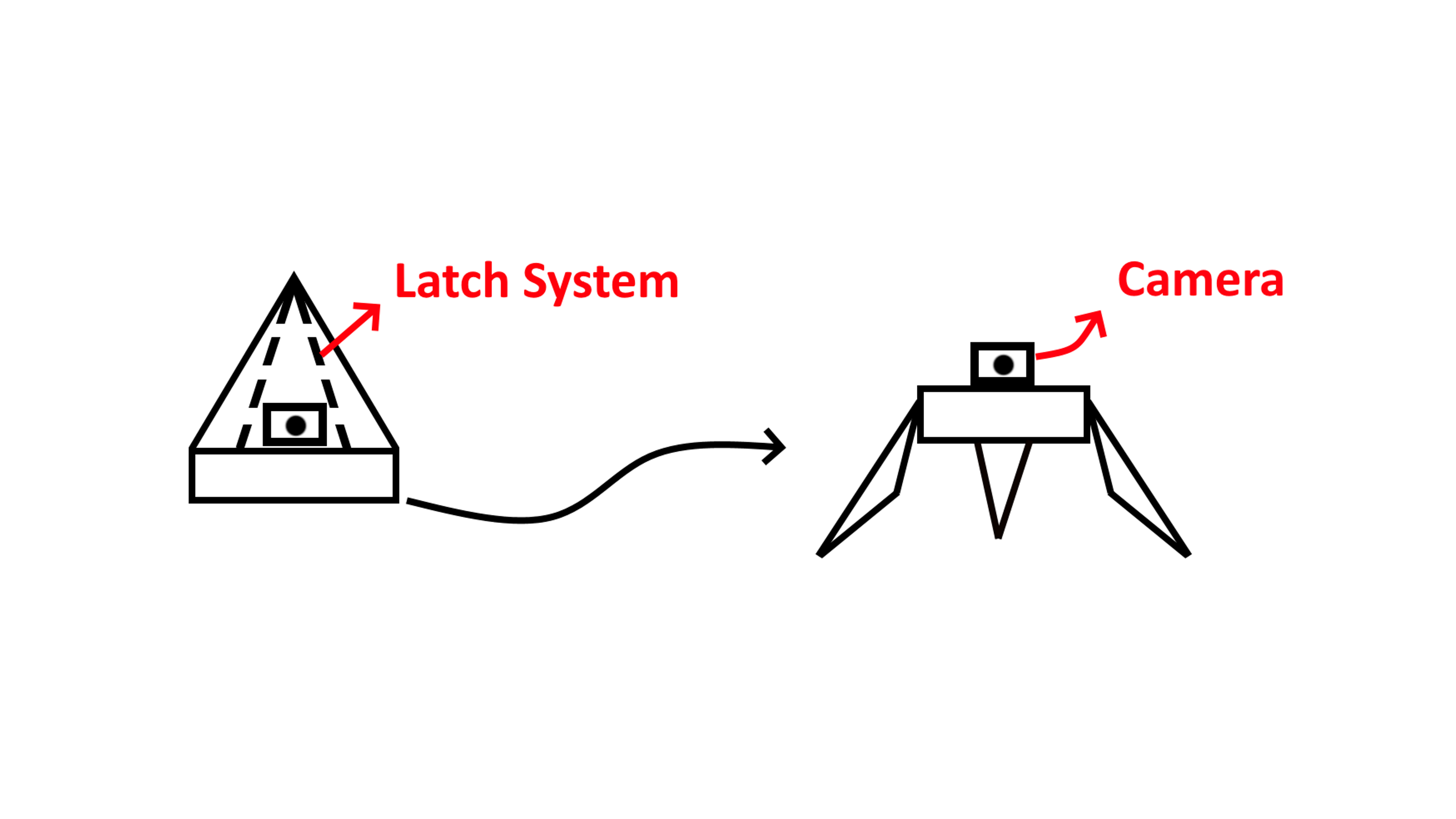
This design utilizes a set of latches composes of 3 equal sections of the rocket's nosecone to right itself upward regardless of how it has landed on the ground. The camera system is subsequently above any potential obstacles present on the local terrain.
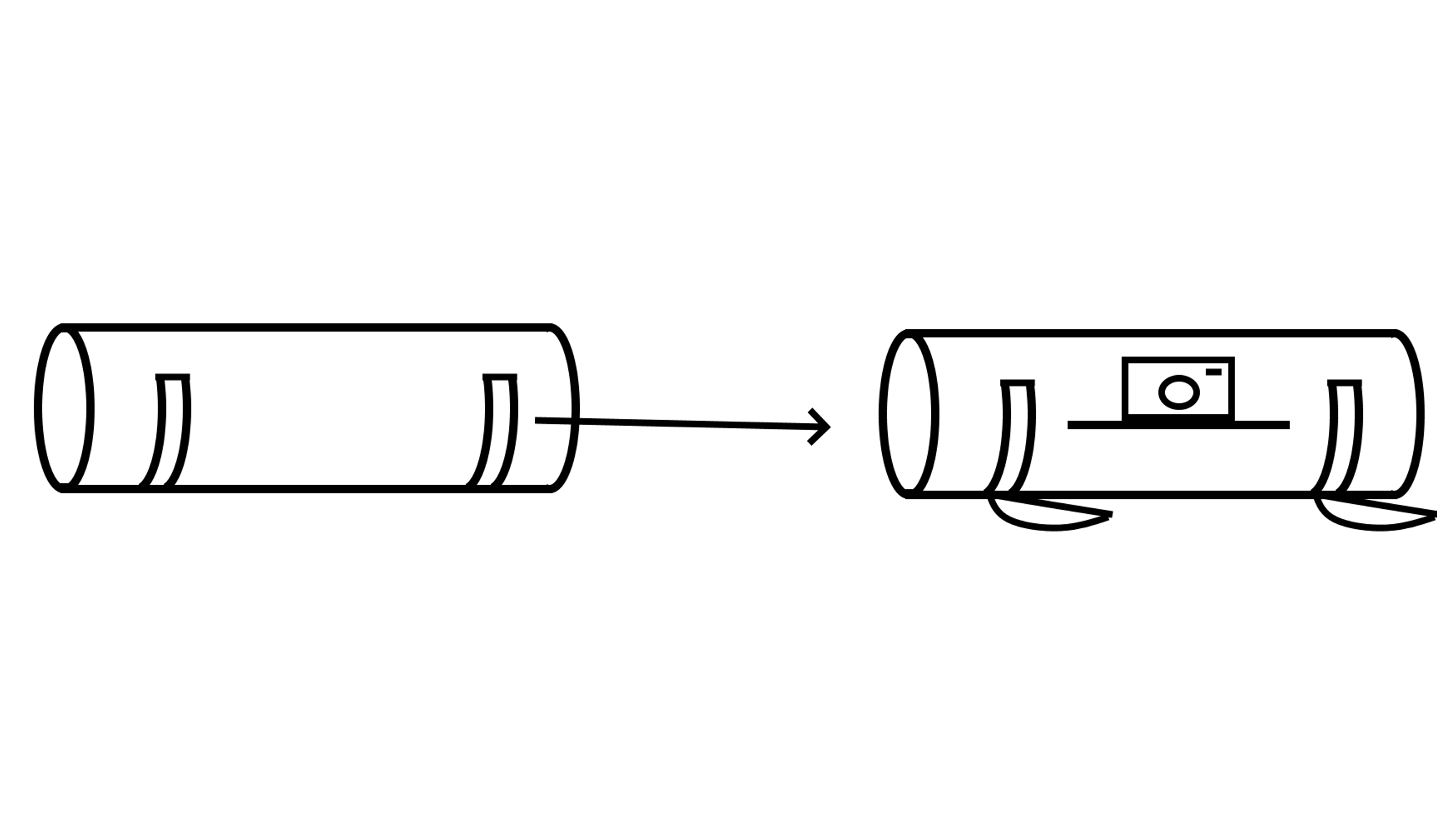
This design features a set of cylindrical legs intended to rotate the body section to be normal to the ground.
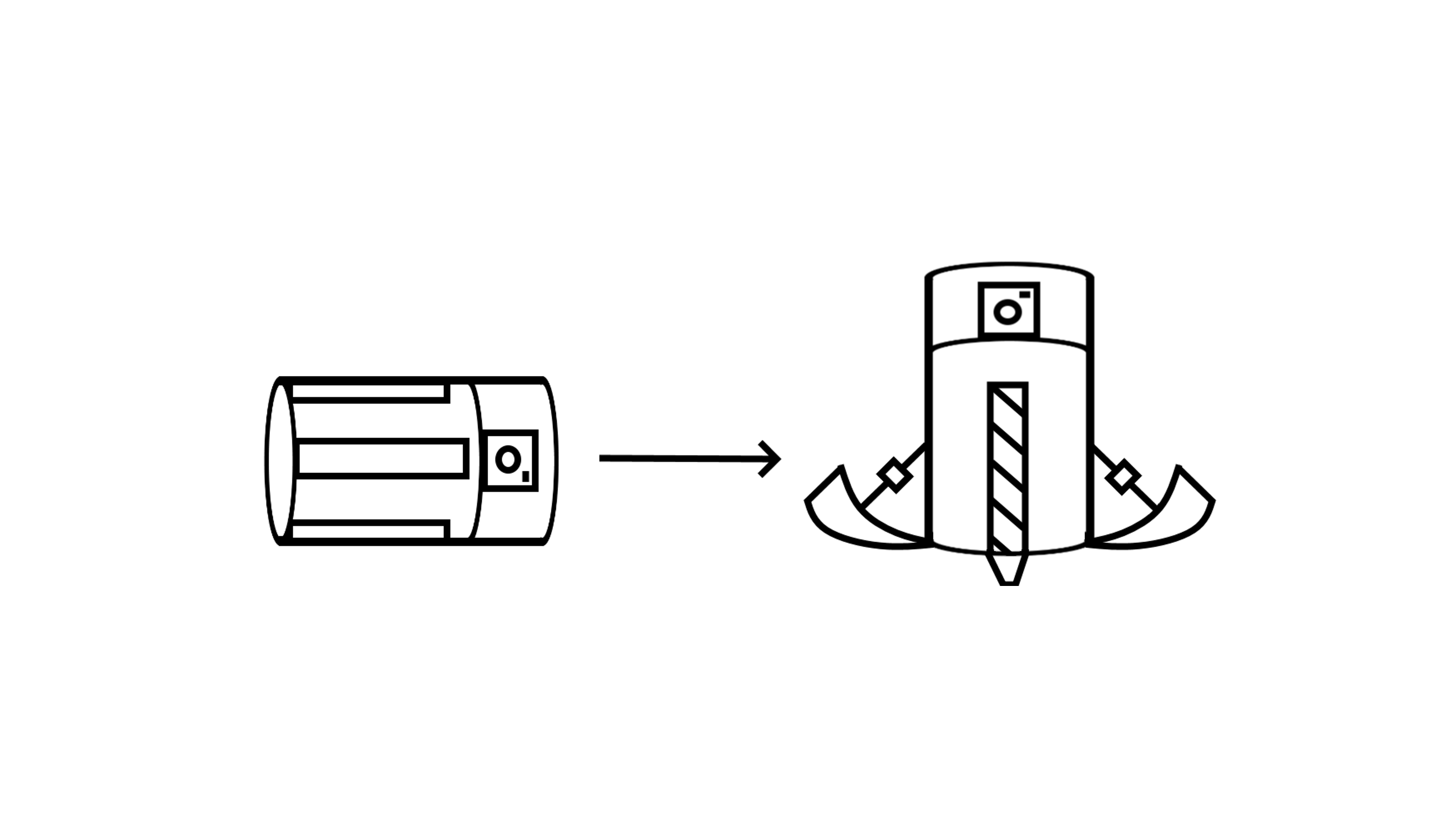
This design utilizes a set of 3 to 4 legs to push itself off of the ground should the payload have landed on its side. The Center of Mass is below the legs, ensuring that the camera system is above any obstacles on the local terrain. The legs are operated by use of linear actuators.
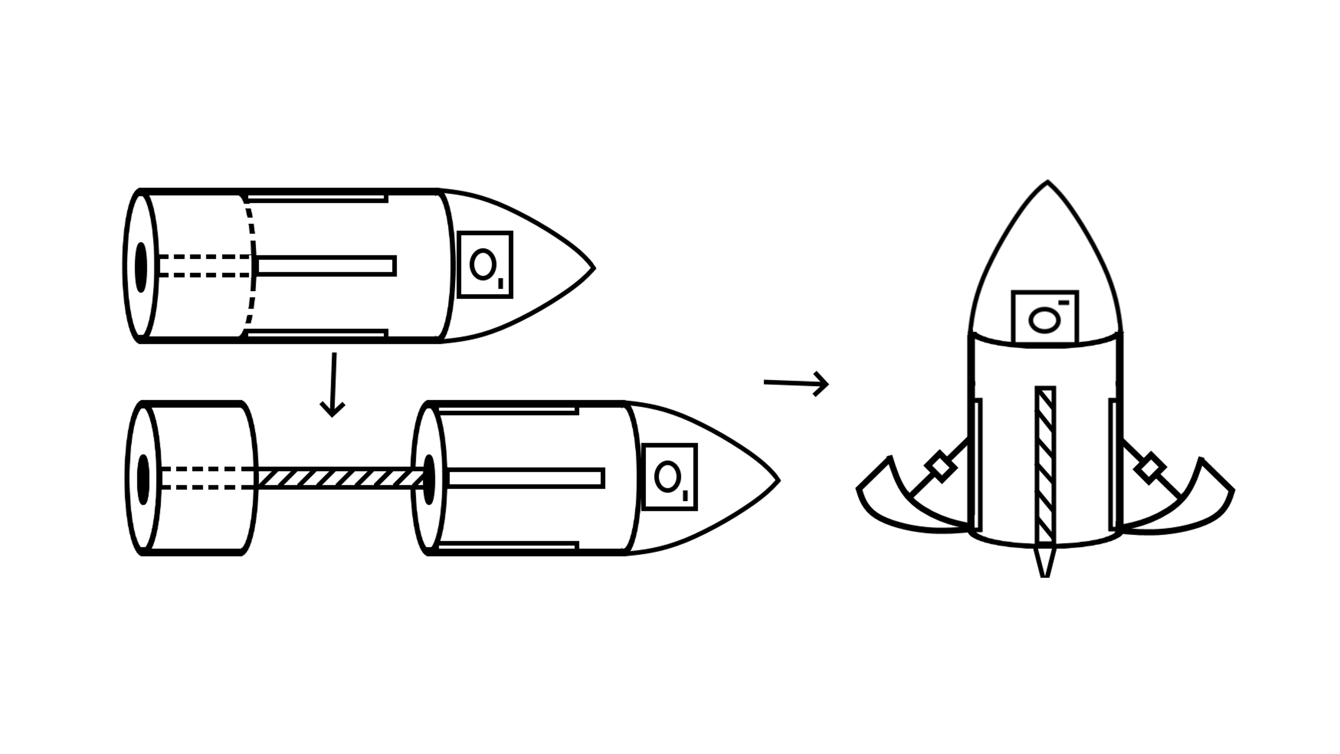
This design utilizes a custom screw system that allows the payload to easily break away from the attached parachute. The subsystem then utilizes a set of 3-4 legs powered by linear actuators to orientate itself normal to the ground. The Center of Mass is below the legs, ensuring that the camera is positioned correctly.
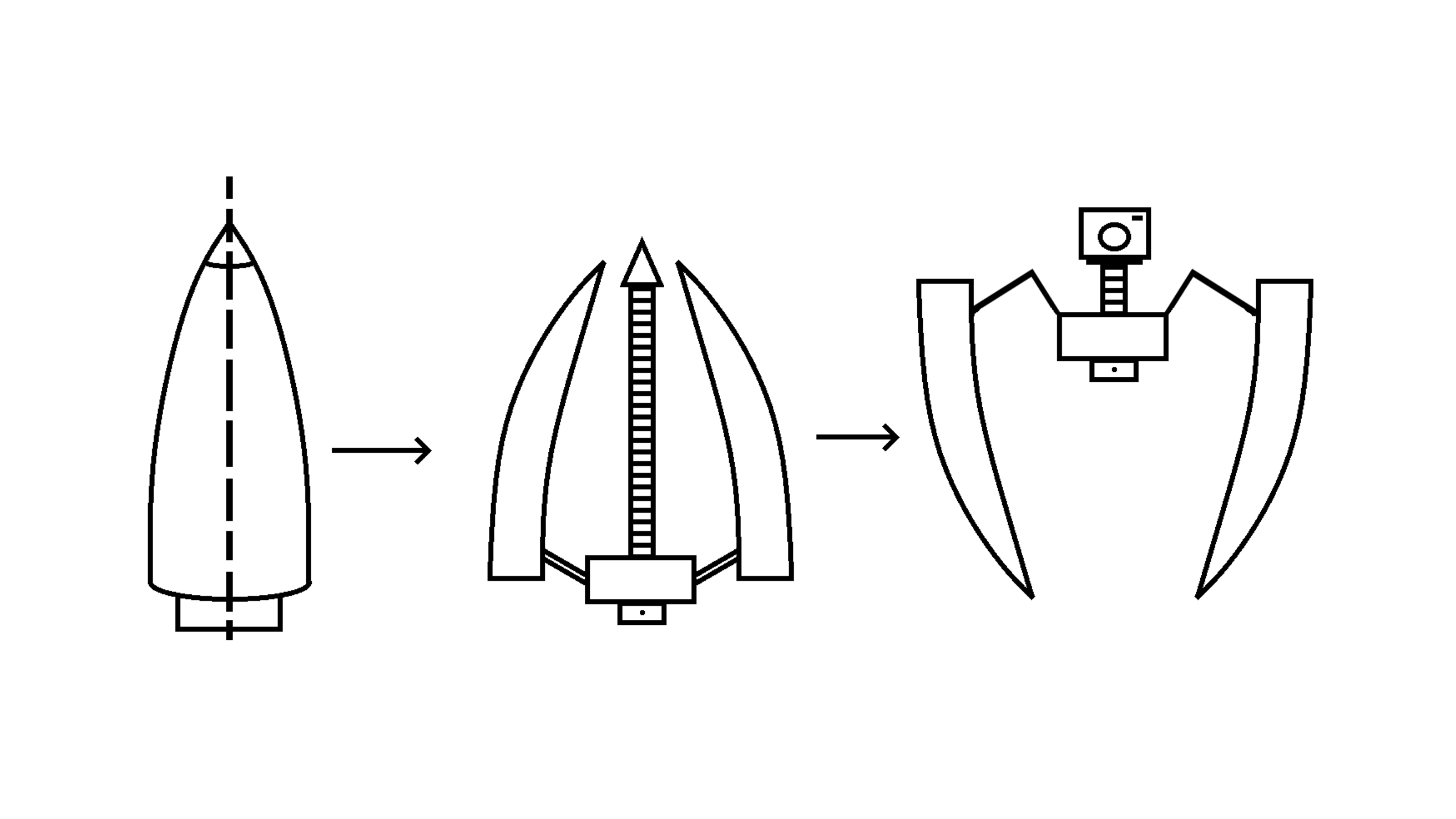
(Code Name: Spidertron 9000) This design focuses heavily on robotics, utilizing a set of legs composed from 3-4 equal sections of the rocket's nosecone that rotate 180 degrees from their initial positions. This method is completed through the use of a twisting mechanism, ensuring that the camera ends up at the top of the robot.
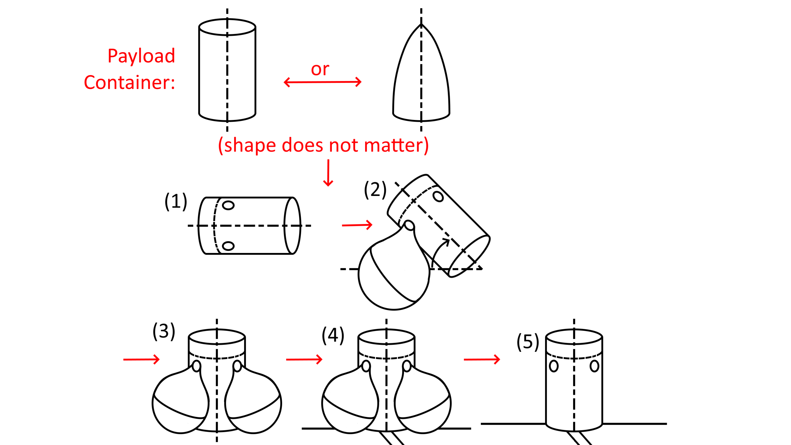
This design utilizes a set of 3 to 4 balloons to rotate itself normal to the ground plane. The Center of Mass is located towards the bottom of the payload, ensuring that the camera ends up in the correct location. The design uses a locking mechanism to push out 3 to 4 rectangular platforms to provide stability as the balloons are deflated.
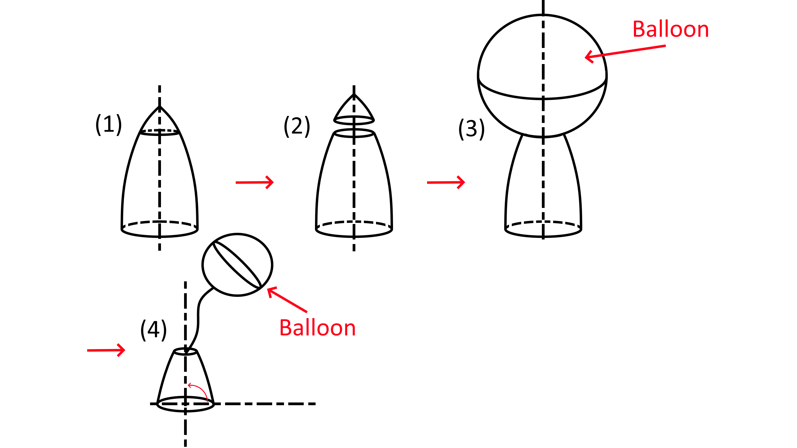
This design utilizes a single balloon to raise the tip of the rocket nosecone above the ground. Importantly, the balloon does not need to carry the weight of the entire payload system. The Center of Mass will be positioned close to the bottom of the payload system such that the balloon only needs to act as a moment arm to completely align the payload normal to the ground plane.
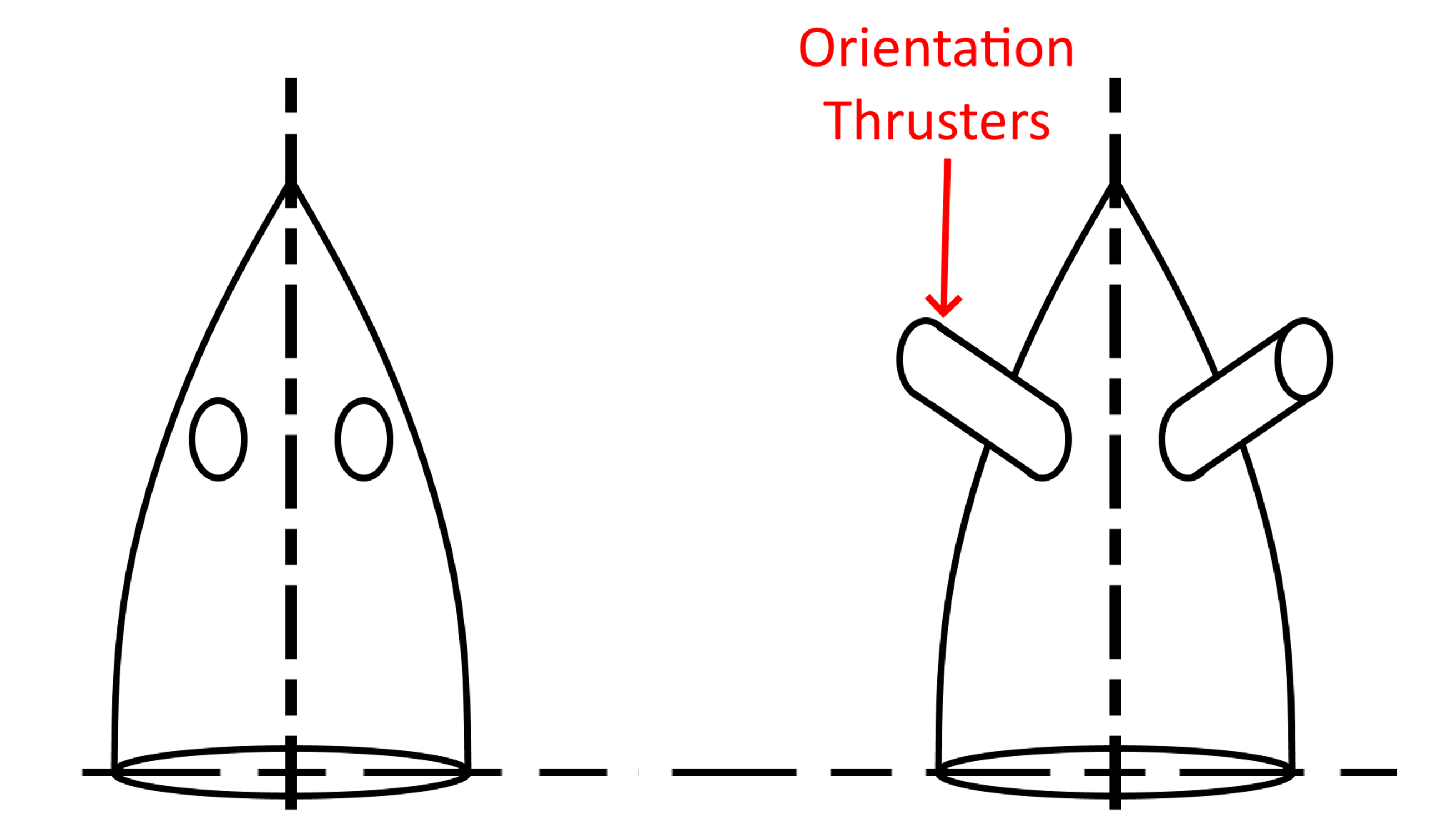
This design utilizes a set of thrusters to forcefully push the payload systems normal to the ground plane. This design performed the worst out of all other Concept Variants as this design would have ignited explosive gasses to accomplish this goal.
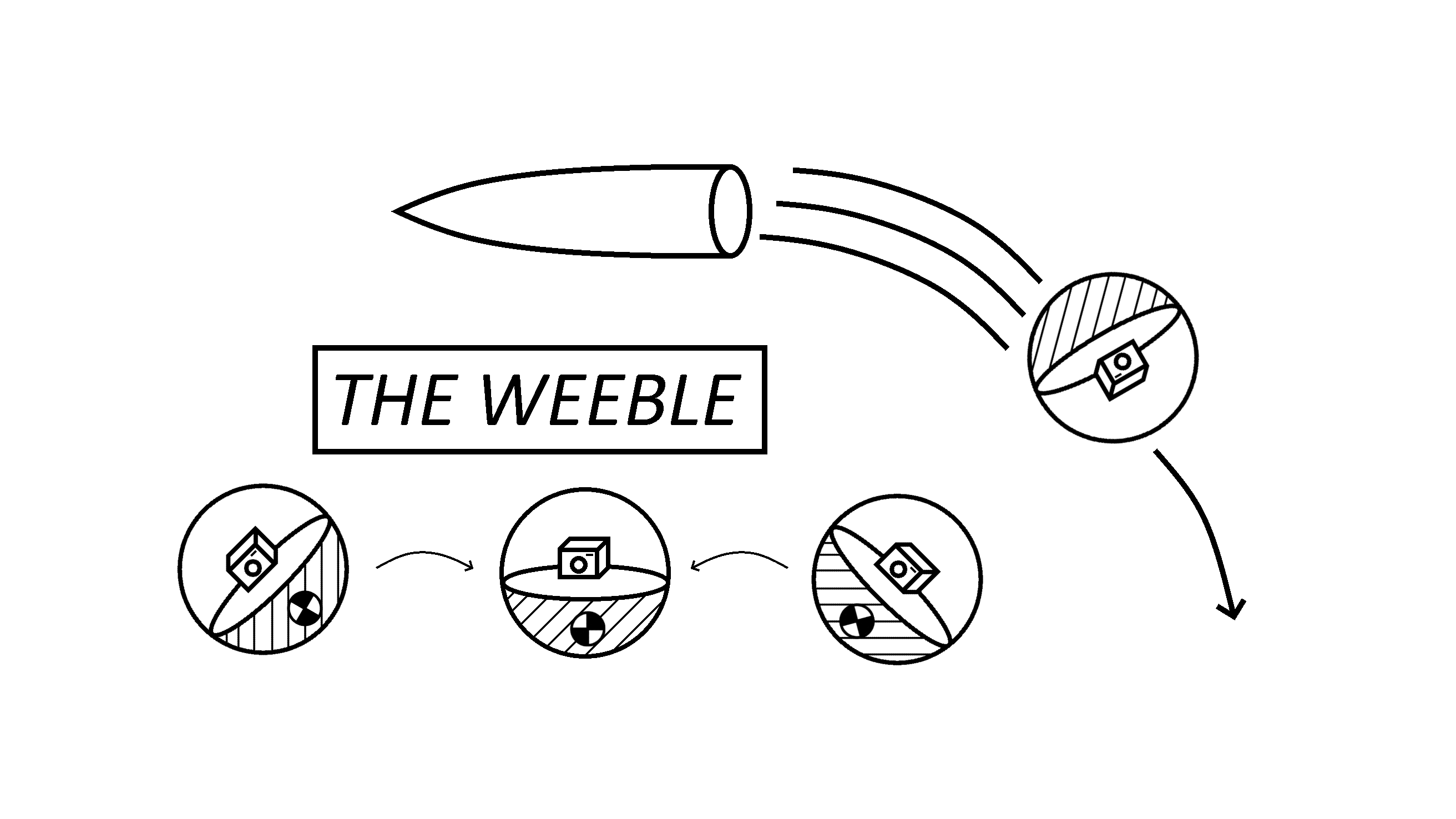
This design relies solely on pasive alignment to ensure that the camera is normal to the ground plane. This design utilizes basic physics associated with achieving equilibrium, wherein the Center of Mass is as close to the ground as possible. This results in the spherical system to rotate and come to rest normal to the ground plane.
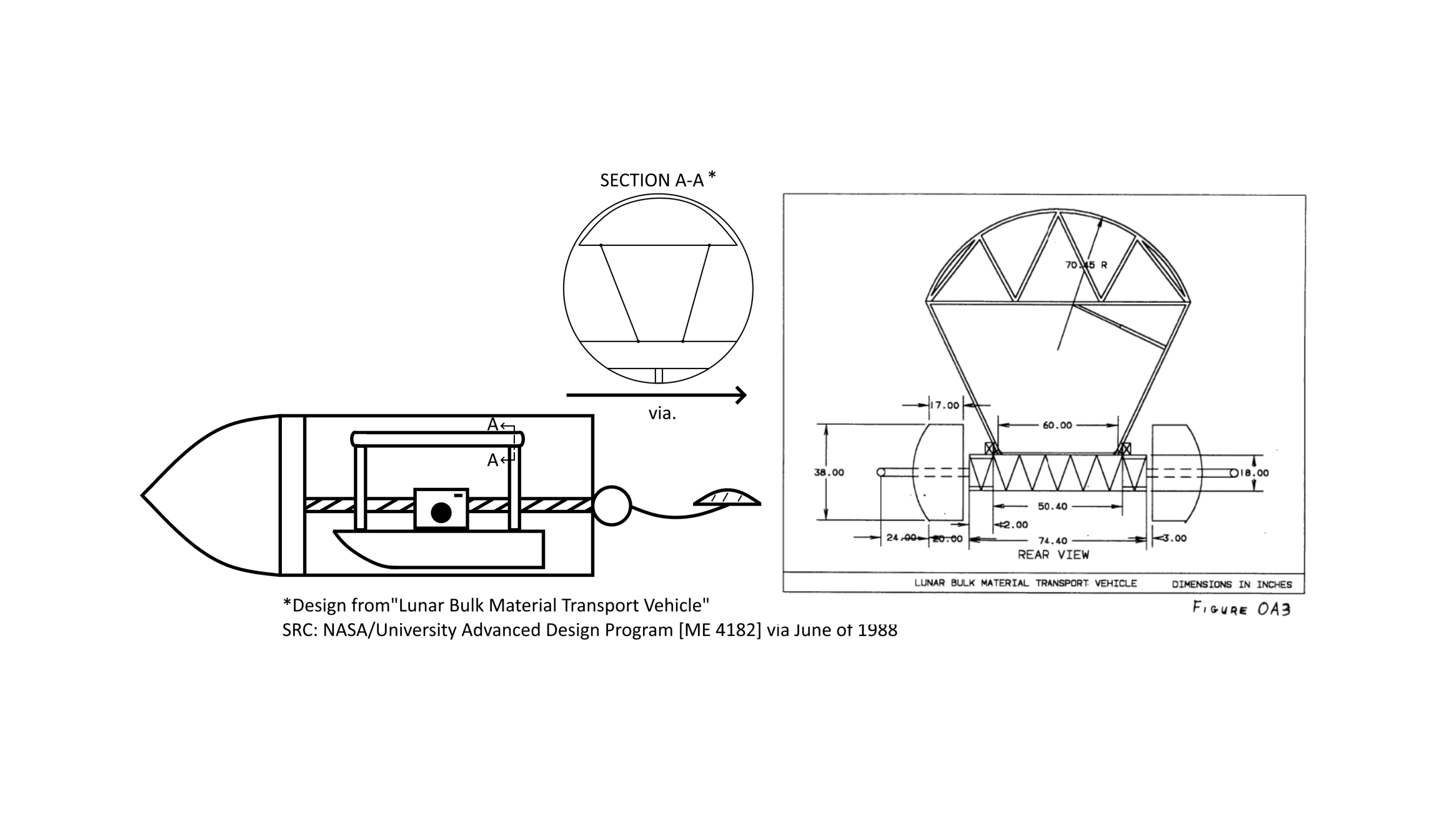
This design was inspired based on a 1988 NASA/University Advanced Design Program. The design incorporates a proposed lunar bulk material transport vehicle's method of proper alignment and applies this proposed design onto a deployable platform which can be removed from the payload transport tube through rotating a custom screw such that the platform is pushed out into the local environment.
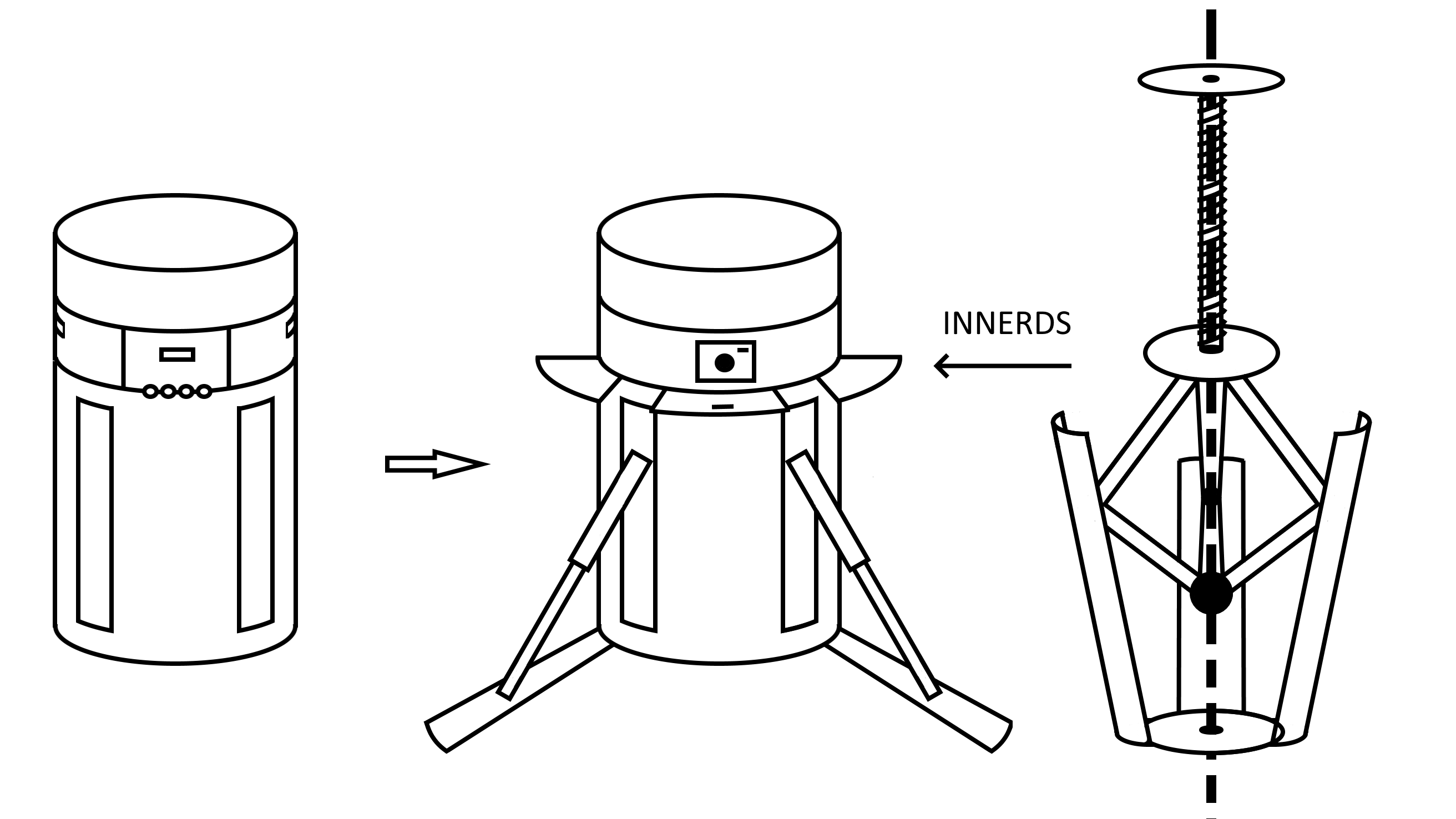
This design utilizes a spring in place of a linear actuator to deploy a set of 3 to 4 legs out from the payload system, allowing for the device to be passively rotated normal to the ground plane.
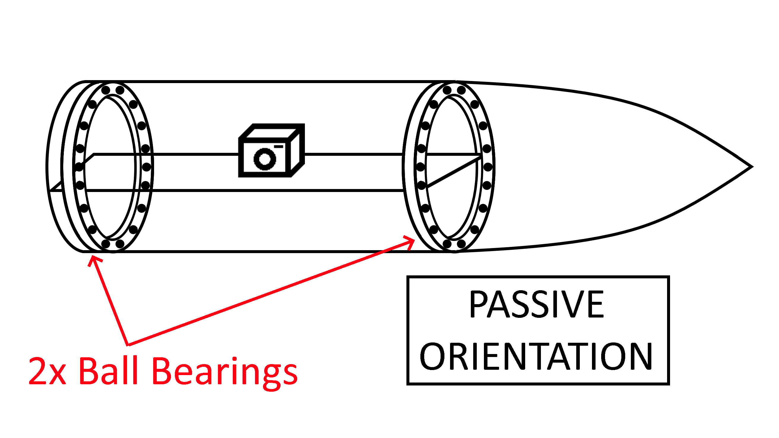
This design utilizes a set of ball bearings to allow the camera system to passively rotate itself normal to the ground plane. The camera systems and platform are designed in such a way that this platform is acts as a gimbal.
As requested by Dr. Carson Pete, the team performed an Analytical Hierarchy Process (AHP) in order to determine what the final design should be. This selection process was utilized due to its allowance of direct comparison of each criterion to develop a weighted eigenvector which would later be applied to the concept variants' scoring, allowing for the creation of a numerical assessment on how well each concept variant meets these criteria.
To make this process easier to follow along with, each step has been numbered in order of completion.
The criterion used within the AHP is depicted below, accompanied by a brief description of the given criterion. These criteria were generated based on the requirements listed by NASA with regards to what the payload is expected to do as well as a handful of logical parameters with respect to the delivery vehicle. These criteria would later be ranked relative to one another.
Criterion |
Description |
| Location (S-mar effect) |
Describes how the location of the additional weight of the payload will affect the overall stability of the transport vehicle in flight |
| Terrain adaptability |
Describes the variety of terrain the design can adapt to, i.e., flat ground, tall vegetation, etc. |
| Self-righting capability |
Describes the design’s ability to orient itself in the active position required for mission parameters |
| Z-axis Alignment |
Describes the design’s ability to align the camera with the z-axis normal to the ground plane |
| Simplicity of Manufacturing/Design |
Describes the depth that will be required to manufacture/construct the design |
| Simplicity of Operation |
Describes the complexity of each required operation within the design while achieving mission parameters |
| Power consumption |
Describes how much total required power the design requires |
| Cost |
Describes the total cost of the design |
| Weight |
Describes the total weight of the design |
| Required Chute Detachments |
Describes the number of parachutes that the design must detach from |
| Structural Integrity |
Describes the influence of the design on the transport vehicle's integrity |
Per the method of the Analytical Hierarchy Process (AHP), the aforementioned criteria were next ranked relative to one another. These criteria were ranked on a scale of 1/9 to 9, where 1 means that the two criteria in question are equally significant with every value being a factor in which the criterion is more important. For instance, a weight of 9 meant that the team felt that the given criterion was 9 times as significant as the criterion it was being compared with, while a score of 1/3 meant that the team felt that the criterion in question was a third as significant as the criterion it was being compared with.
The final relative scores are depicted below. Each criterion listed on the vertical axis was ranked relative to the criteria depicted across the horizontal axis.
Once the criteria were ranked relative to one another, they were normalized. This was done in order to generate a weighted eigen vector which would be applied onto the ranked concept variants. The normalized criteria rankings are depicted in the image below, with the normalized principle Eigen vector listed to the right of the table.
The previously generated Concept Variants (shown under Concept Selection) were next ranked based on how well they met the previously generated design criteria. The "Chute Detachment" criteria was a point of heavy discussion, and was subsequently considered a "grey area." The team ranked each concept variant on a case-by-case basis, ensuring to assess 1. how many cutes the concept variant would need to detach from, 2. how easily the concept variant would be able to detach from these chutes, and 3. how difficult it would be to include a method of parachute detachment.
The team's final rankings for each Concept Variant is listed below.
As is required with the Analytical Hierarchy process, The aforementioned concept variant rankings were then normalized. The normalized rankings of these concept variants were required in order to properly compare them with the principle Eigen vector, which was generated in Step 3. Finally, the principle Eigen vector was then multiplied into each concept variant's normalized scores to generate a final assessment of how well each concept variant would meet the team's engineering requirements.
The finalized scores for the concept variants are depicted below. The Preference Rank is on a scale of 1 to 14, with 1 being the first place position for the concept variant's preference score, and 14 being the last place position.
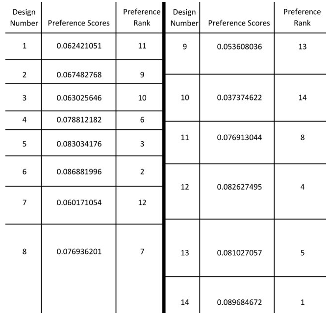
As determined from the Analytical Hierarchy Process, CV14 was deemed to most adequately meet the required design parameters. As described within the above image gallery, this Concept Variant uses a set of ball bearings to allow the camera system to passively rotate itself normal to the ground plane. The camera system and platform are designed in such a way that this platform acts as a gimbal.
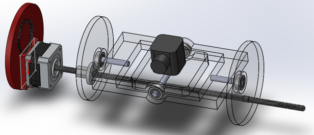
The rough CAD model for Concept Variant 14 is depicted to the right. Shown is the proposed method for chute detachment, which utilizes a motor to rotate a threaded rod, allowing for the payload system to be ejected from the rocket body. This system will also include two pairs of ball bearings such that the camera is able to gimbal with 360 degrees of movement.
As a part of the design process, the team created a Preliminary Design Report (PDR) for the NAU Rocket Club to incorporate into their NASA PDR submission. This report is viewable by clicking on the image to the left, and contains the progress of the design process as of October 2022.
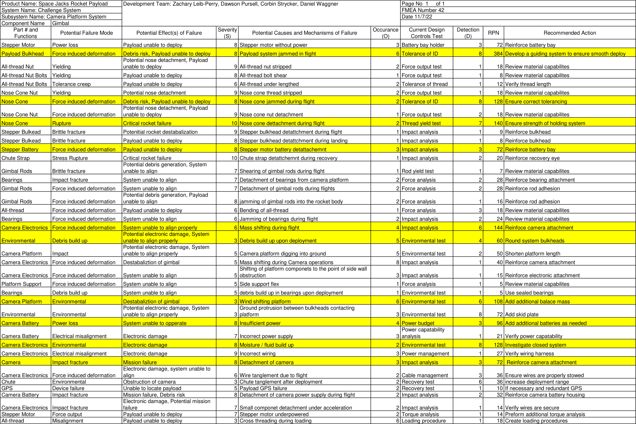
Headed by Dawson Pursell, the team conducted a Failure Mode and Effects Analysis (FMEA) in order to better prepare for any potential areas of design failure. 40 modes of failure were identified and assessed, with the subsequent results being depicted below.
Some of the most important modes of failure were regarding physical component failure. According to the conducted analysis, these modes of failure are likely to be caused by force-induced deformation, the effects of a critical rocket failure, damages caused by uncontrolled impacts, and various environmental factors.
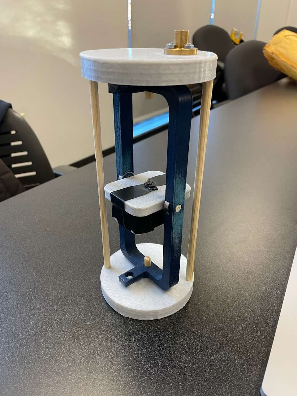
The team would eventually design 3 different prototypes. The first prototype was designed around late November / early December 2022. This prototype focused heavily on the overall passive orientation systems that the team had in mind. The second prototype was generated as a midway step while constructing the final design. This prototype allowed the team to ensure that 1. all critical gimballing components were properly aligned and 2. that the selected design passed very basic sanity checks. The final prototype that the team generated served to ensure that the design process foe the deployment bay was sound, and that the bay was compatible with the required electronics needed to be employed by the Electrical Division. More information regarding the team's prototyping methods are outlined in the Final Design section of this website.
The image to the right shows the team's first designed prototype. This prototype allowed the team to view the feasibility of using a passive orientation system to align the electronics properly with respect to the Earth's gravitational vector. Due to errors within the design process on the side of the Electrical Division, the final design would be modified extensively to allow for the inclusion of a 6-inch antenna. The team took great pride in this prototype, as it was the first prototype that they had come up with.
As requested by NASA, the team assisted the NAU Rocket Club on their CDR submission. The team contributed to documenting their current progress within the overall design process within Section 5. Importantly, the Electrical Division's progress was also outlined in extreme detail. This report is viewable by clicking on the image to the left, and contains the progress of the team's design process as of January 2023.
The team's payload systems went under numerous various hardware, software, and electrical subsystem testing variations in order to ensure that all systems were operating both as intended and with reliable repetition. These tests were broken up into 2 categories: structural testing and electrical testing. The Structural testing focused on ensuring that the payload was able to support the entire weight of the rocket (more on that below), while the Electrical testing focused on ensuring that all critical sensors were operating correctly. The Electrical tests saw the design of 2 experimental apparatuses that each tested a specific sensor.
This method of testing focused on ensuring that the payload system was able to adequately support the entire rocket while descending. The selected design used a NEMA 17 Stepper Motor, which was connected between the nosecone and the avionics systems. As such, the threaded rod that the Stepper Motor used was the sole connection between these two critical systems.

Depicted (Left to Right): Parachute Chord Hook, Deployment Bay with NEMA 17 Stepper Motor, Deployable Payload System, Rocket Nose Cone. Note that the NEMA 17 Stepper Motor's Threaded Rod goes the entire length of the system, from the deployment bay to the interior of the nosecone.
Multiple test flights were conducted using a "skeleton" of the payload systems. This "skeleton" solely consisted of the primary payload supports and the NEMA 17 Stepper Motor. All other critical systems were not included, as the team was concerned that, if something went wrong and this support system failed during descent, the Electrical Division's components would become irreparably damaged. The Mechanical Division's components were, aside from the NEMA 17, relatively easy and cost-efficient to replace, while the Electrical Division's components were extremely expensive.
The employed system worked phenomenally, and the NEMA 17 Stepper Motor was able to support the entire weight of the rocket with no issues whatsoever. The NEMA 17 Stepper Motor would continue to perform well throughout all other launches.
This test served to ensure that the payload’s altimeter was properly functioning. The altimeter was the first of 2 redundancies employed by the payload and served to detect if the rocket and her payload had been launched by comparing the payload’s current height to its initial height. Upon exceeding a height of 1,000 ft and upon returning to a height within 75 feet of the initial height, the transducer reports to the primary computer systems that the rocket has been launched and has landed.
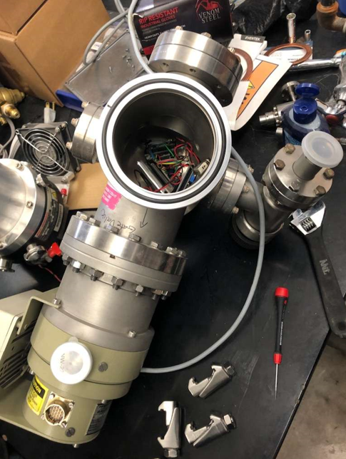
These tests were conducted using NAU's physics department's vacuum chamber, depicted above. The deployment bay was placed inside the vacuum chamber, wherein the pressure was reduced for between 5 and 7 second, ensuring that the pressure changed enough to simulate an altitude change of at least 5,000 ft. The altimeter functions by measuring the local pressure around itself and computing that directly into altitude readouts. By using a vacuum chamber, the team was able to reliably create a controlled system wherein the altimeter could be evaluated under identical conditions as if it were in flight. The sensor's code was modified and revised to ensure that the system was both correctly reading the relative altitudes and that, upon reaching this height and upon returning to its initial height within 75 feet, the motor driver would be initialized.
This test served to ensure that the payload’s accelerometer was properly functioning. The accelerometer was the second of two redundancies employed to ensure that the payload would not deploy prematurely. This is done by measuring the magnitude of the device's experienced acceleration. The system has 2 steps. first, the device ensures that a minimum of 5 G's has been measured. Once this condition is met, the device waits to see that it is currently experiencing 1 ± 0.05 G's for a minimum of 5 seconds.
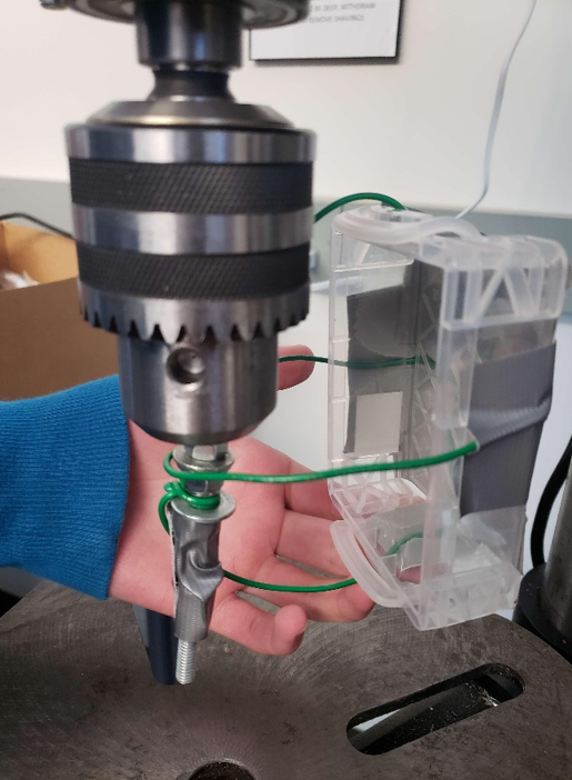
The Mechanical Division generated a make-shift centrifuge (depicted above) to simulate high values of local acceleration. Using the concepts of centripetal acceleration, the team ran the drill press at around 680 RPM with a distance between the accelerometer and the center of rotation measuring between 2 and 3 inches. Back-handed calculations informed the Mechanical Division that the sensors should be reading between 24- and 39- times Earth's acceleration. These calculations were compared with the accelerometer's readouts, and the sensor was modified to ensure that it was correctly displaying its measured acceleration. Once this was confirmed, the system was evaluated to ensure that, upon the aforementioned conditions being met, the motor driver would be initialized.
After months and months of designing, testing, and iterating, the team had finalized their design just in time for the Alabama NASA Student launch competition.
The team's design utilizes both passive and active orientation capabilities to ensure that the Electrical Components of the challenge system are able to adequately receive and act upon various transmissions delivered by NASA. The system uses a passive quadruple-bearing gimbal system to passively rotate the electronics normal to Earth's gravitational vector. This system also has a protective cover that spins down first to ensure that the electronics are not damaged by debris. The system then employs an active motor to elevate a camera platform such that both the camera and the antenna are above the local surface, ensuring reliable surveillance and transmission capabilities. The design also includes a Rotating Thread-Rod Deployment System (RTRDS) to completely separate from the transport vehicle during deployment. The RTDS uses a NEMA 17 Stepper Motor to push the payload out of the rocker body tube, preventing the systems from being damaged as a result of the rocket's parachutes pulling the system to various areas.
The final design is depicted in greater detail under the Final Design page on this website.
After months and months of designing, testing, and iterating, the team is extremely happy with how well their design turned out. This process reinforced every concept that they have had hammered into them over their entire degree program and, overall, the design itself is well-thought-out and well executed. This experience will prove to be priceless as all members of this design team move into industry and/or continue furthering their education.