NASA Lunar Surface Habitat Research
The concept of suriving on a foreign planet for the first time in human kind history is not a light subject. Thus, this team has spent numerous hours researching the reality and consequences of habilitating the Earth's Moon in order to one day reach Mars. The team has covered all subjects that would potentially have consequences on human life while visiting the planets. One of the most life threatening risks is the radiation that exists outside of our home planet. With no atmosphere to protect the astronauts from radiation, air pressure, micrometiorites, air temperature differentiation, etc. scientisist, engineering and everyone who dreams of reaching other planets outside of Earth, must work hand in hand in order to make this impossible dream a reality.
Through past trips of multiple Apollo missions, rovers, and thousands of other essential researching tactics, the team was able to pin point certain criterias that will be utilized throughout the projects duration. The most essential customer requirements that the team will prioritize first is the safety of the crew members throughout the duration of the mission, the ability to fit all the materials and habiliatation requirements onto the roket due to finanicial restrictions, and keeping the design on the concepts safe and secure from the radiation through the use of a radiation shield.
Once the astronauts have reached the surface of the moon, engineers must have a clearcut plan for how they will survive throughout the duation of the mission. Being able to sustain the ship with the required power is an essential component of the desing that has no room for failure. The team has constructd multiple different designs for the power generation. Some of the most promising concepts included a small nuclear power generation model, solar panels, and a hydrogen fuel cell. Although, all sound extremely useful on their own, the team is also considering the possibility of including all desings simutaneously.
As mentioned, the insulation material will be an essential aspect of the design due to the exteme radiation levels and the fluxuation of weather temperature. Thus, the team has weighed options for the portective materials very carefully. Thus far the concept of including lunar regolith on the outer surface of the habitat design while including Mylar and Kapton within the inner design woulf potentially provide the team with the most sustainable and protective design.
Radiation Analysis
In order for the habitat to be safe for astronauts, it must be able to mitigate radiation flux through the outer and inner layers of the structure. In order to accomplish this, a basic calculation will be performed to figure out how much radiation flux the habitat will be exposed to on the moon. This can be determined easily using the following formula: Φ=L/4πr^2 in W/m^2 where L is the luminosity (in this case the suns luminosity), and r is the distance from the moons south pole to the sun. Luminosity can be calculated using L= ϵσAsT4s assuming epsilon = 1 because the sun radiates like a blackbody. The distance r was calculated using geometry knowing the moons tilt, the moons radius, and the distance at which the moon is from the sun. This radiation flux value can be integrated over a time period to determine the radiant energy (J/m^2) that could be expected to design for. Since this distance changes, and the radiation flux is typically a function of the distance and the solar cycle, assumptions will have to be made based on the closest possible distance the moon will be to the sun. This is to ensure that the design will be for the maximum value of radiation flux. Next, materials like polyethylene, RFX1 (which is a new kind of polyethylene plastic), Kevlar, and lunar regolith will be considered for their properties in absorptivity, reflectivity, and transmissibility to determine which material would have the highest rate of radiation mitigation. The material with the highest combined reflectivity and absorptivity, and the lowest transmissibility will be the most effective. Combinations of materials with different layers will also be considered, as it could have benefits using different materials to mitigate neutron and electromagnetic radiation. Specifications will be made for optimal thickness values along with a factor of safety for each design.Life Support System- Water Process Assembly (WPA)
In order for humans to venture off in deep space to fulfill our unprecedented curiosity, engineers and scientists must create the perfect sustainable habitat that has an efficiency of 100%. The International Space Station (ISS) consists of a Water Process Assembly (WPA) and Urine Process Assembly (UPA) that have been in functioning for over 15 years but still lack to reach a proficient efficiency rating of over 98%. Within this individual analysis, the specific amount of water required on board the lunar habitat has been designated through precise measurements and the process of the lunar habitat’s WPA and UPA have been broken down. Many minerals and compounds are left untreated throughout the current model’s assembly on board the ISS. The UPA has an individual process of refining the urine before mixed in with other wastewaters in a storage tank in WPA. The current UPA model requires constant maintenance as the system fails to filter CaSO4 where in turn a hard precipitation forms around the walls of the filter and the efficiency rating have dropped significantly to 70%. With a replacement of H3PO4 and H2SO4 , the efficiency can climb to 90%. The extraction of the UPA is then transferred to the Water Processor Assembly (WPA) where it is mixed with all the other wastewaters such as washing, housekeeping, and the precipitation of humidity from the climate control system. All the combined liquids then move into the initial stage of the WPA where smaller contaminants like hair, dust, skin cells, etc. are extracted and then degassed using a Rotary Gas Separator (RGS) which has an efficiency of 98%. RGS designs allow the flowing water and gaseous combination to flow into a rotating centrifuge with inducers and straight vanes. As the flowing liquid approach the centrifuge, the denser compounds like water move to the outside, and the lighter compounds such as free gas move to the center of the centrifuge. The liquids then flow into a multi-filtration bed where organic compounds are absorbed, and ionic compounds are removed via an ionic exchange process. The liquids then flow into a multi-filtration bed where organic compounds are absorbed, and ionic compounds are removed via an ionic exchange process. The liquids then flow into an Aquaporins (AQP) process where organic compounds are absorbed, and ionic compounds are removed via an ionic exchange process. AQPs are a series of transmembrane protein whose class is found in every organism and represented in every taxonomic group. The AQP has the potential rejecting 100% of all compounds except for water through a solute-impermeable stable matrix. The module then proceeds to flow the harvested liquid to a catalytic oxidation reactor. Within, the liquid will be oxidized with the presence of oxygen, high temperatures of 130°, and a catalyst, removing the micro-molecular weight organics. This assembly has shown an efficiency rating of 97.9%. Finally, sensors implemented within the WPA regulate the pH level of the water and if the level falls within 6.0 to 8.5, the water is released into an exterior water tank where it is made readily available for the astronaut’s usage.Structural/Impact Analysis of Micrometeorite Shielding
Conducting structural/impact analysis on the integrity of our micrometeorite shield is imperative to ensuring the safety of our astronauts over the course of the 30-day mission. Understanding how an impact from an object moving at hypervelocity speeds can affect the efficiency of our shield will allow our team to design a strong exterior safeguard that can withstand such conditions. Our team has decided to base our shield design off NASA’s Multi-Shock Whipple Shield which is a derivative of the Whipple Shield. This shield once impacted by an object continuously shocks the object until it is completely vaporized. Luckily, we already know that this shield has been proven successful through rigorous testing at the Johnson Space Center Hypervelocity Impact Research Laboratory. It is also currently being used on the International Space Station (ISS) to protect the astronauts from micrometeorites. So, to properly create a strong shield that will continuously shock the micrometeorites we will need to analyze the atmosphere of the lunar surface. The reason for this is because we need to calculate the speed of sound at varying temperatures and specific heat ratios. This will allow our team to obtain the Mach number and thus the Mach angle. Once the Mach angle is obtained this will give us an indication of how strong the shock waves will be within our Multi-Shock Whipple Shield. We will also need to analyze various materials as well as how micrometeorites will affect our shield when it impacts at an oblique angle or a normal angle. Lastly, we will need to account more parameters (i.e., Force, Kinetic energy, Momentum, Stress (Tensile & Shear), Pressure, Impulse, and Heat energy). Further research and analytical calculations are needed to present evidence that our shield will be more than adequate for the task at hand.Static Structural, Thrust Vibration, and Vibration Fatigue Analysis
Since the initial rocket testing, the thrust to weight ratios for rockets have been improved considerably. The with the added thrust, a number of engineering problems arose. One of the major problems is the self-excitation vibration whereby the vehicle structure and the propulsion system achieve resonance. As a result, most rockets are limited to an acceleration of less than 32m/s^2. A common combustion instability vibration effect is the ‘Pogo’ effect (named after the pogo stick). The effect is also known as the thrust oscillation and usually occurs after the first burner is detached from the rocket. One way to reduce the vibration effect is to conduct vibration analysis on the structure so as to reduce the possibility of sympathetic relationship with the propulsion system.
As a result, conducting vibration simulation is the chosen topic for the individual analysis. To objective is to find if the lunar habitat structure will be able to wither the take of forces acting on it. This will be performed by conducting static structural analysis using Ansys. The maximum acceleration of the flacon heavy found during testing will be used to find the force that will act on the structure. The structure will be tweaked to ensure that structure conforms to the client and engineering requirements. Then Modal Analysis will be performed to determine the natural and resonance frequencies. Random vibration analysis will then be performed by uploading the vibration loads seen during a typical thrust oscillation. This will determine the added stress due to vibration loading and ultimately find the fatigue life of the structure. A general model has been determined to model the analysis by to ascertain that the analysis is possible. A picture of the structure and the initial vibration modeling is provided below.
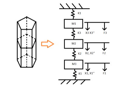
Figure 1: Initial Structure to Vibration Model
In the figure above, the model shows 4 springs attached to the masses. The springs K1 are the support springs placed in the rocket payload module to support the module. This is a 3 degree of freedom model and analysis conducted uses the full structure shown. Below is the pressure wall stress analysis done on ANSYS.
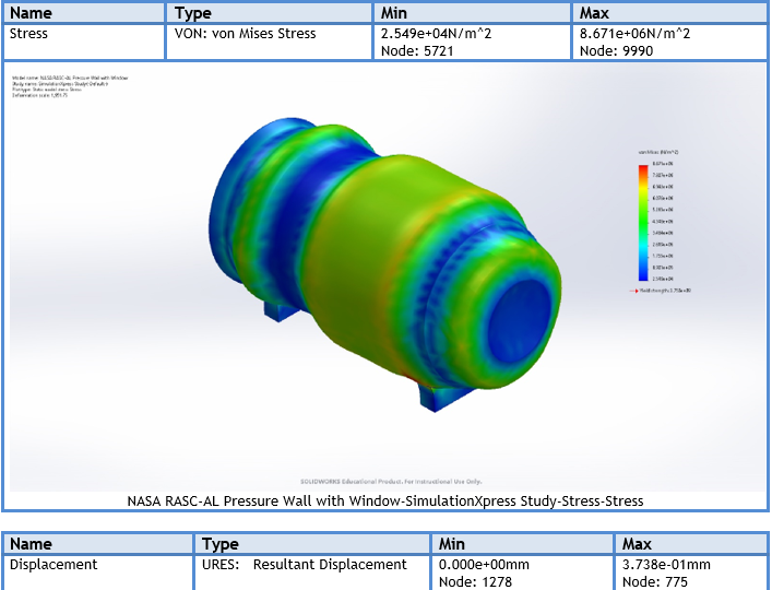
Figure 2: Stress Wall Pressure Analysis
Whipple Shields
The Whipple Shiel's design is intended to protect the habitat the the crew members from micrometeriorites and the toxis radiation levels that emit from the sun. The final iteration of this shield proposses a cylindrical design that would only protect the upper portion of the habitat and come dow, touching the Lunar Surface and displaying an "A" shape. The shield would now have a rectangle geometry which would be placed along the hexagonal bone structure from edge to edge on the top half. At the vertices that separate the upper half between the lower half of the hexagonal bone structure will be hinges that connect the upper portion of the Whipple Shield to the lower portion. This lower portion of the shield will swing in and will hook into the habitat so that it can fit into the Falcon 9 rocket for transportation from the Earth to the Moon. Shortly after placing the habitat on the lunar surface the lower portion will swing open to provide extra protection from micrometeorites, provide storage space for our lunar rovers, and storage space for extra scientific equipment.
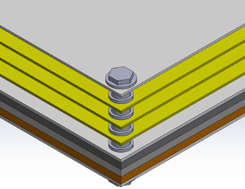
Figure 3: Whipple Shield
Radiation Reduction
An analytical approach was taken to confirm the amount of radiation reduction would occur with the multi-layer insulation (MLI) shield present. The Stephan-Boltzmann law was used to determine the temperature of the outside of the habitat due to the radiation flux from the sun. This is shown in the equation below.

Where Φ is the radiation flux from the sun, approximately 1422 W/m^2 K and σ is the Boltzmann constant. T_1 was determined to be 125°C. Equation 13.28 from Fundamentals of Heat and Mass Transfer 8th Edition, will be used to determine how much electromagnetic radiation energy the astronauts would see inside the habitat, and determine how much the MLI shield reduces the flux by.

This was adopted to the nomenclature shown in the figure below. Figure 4 is a picture of the MLI shield and thermal radiosity network that represents the picture.
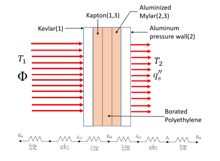
Figure 4: Multi-Layer Insulation (MLI) Diagram
It was determined that the astronauts would see approximately 15.4 W/m^2 of radiation flux which is an 84.4% reduction from the flux calculated without the shield. This fulfilled our radiation reduction engineering requirement benchmarked from the ISS which was about 60%
Heat Rejection
The life support systems necessary to the survival of the astronauts put off an excessive amount of heat within the habitat that will not leave due to the MLI shield which also keeps heat in. For this reason, it is necessary to adapt a climate control system that can pull heat directly from the life support systems and eject it into space via radiation. The International Space Station uses a similar method, which was used as inspiration for this design. The figure below shows a diagram created to better understand the ATCS (Active Thermal Control System) proposed.
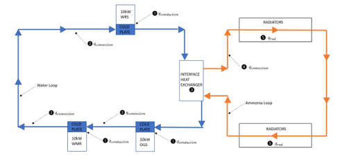
Figure 5: active Thermal Control System
The first equation you see was derived from the first law of thermodynamics to determine the amount of heat that could be exchanged through the heat exchanger. the next equatopm was adopted to determine the amount of radiators required to radiate off all of the heat exchanged from the interface heat exchanger.

These equations resulted in a heat exchange rate of 33.5kW and 16 4m x 1m radiators necessary to radiate all the heat. This clearly meets the requirement of 30kW which was determined from downscaling heat generation values from the ISS
