NASA Lunar Surface Habitat Concept
The lunar habitat has gone through a substantial makeover in the past several weeks. Both major and minor changes were made to the design based off meeting engineering requirements, FEA (Finite Element Analysis) analysis, and learning manufacturing techniques from constructing the scaled prototype. Some of the larger changes include redesigning the bone structure, removing the internal wall, and redesigning the Whipple shield. The remainder of the design changes are minor and were made to work with the new major changes made. Certain design changes were implemented to the physical prototype the team is designing to save costs and make the process feasible.
Two key design iterations were conducted on the bone structure. The first pertained to the cross section of the bone structure. Initially, the bone structure was designed as rectangular beams. After the implementation of the pressure wall, the plate structure carried too much weight. As a result, the structure was changed to circular tubing which is easier to weld and would limit stress concentrations. The figures below illustrate the previous and latter designs.

Figures 1&2: Bone Structure Design
In addition to the cross section, the hexagonal shape of the bone structure was analyzed to improve the integrity. A key assumption was that the weld material used was assumed to have the same properties as the metal itself. The figure 30 below illustrates the analysis done on the one of the subsections of the bone structure. The force chosen was calculated from the internal pressure of 101300 N/m2 * half the surface area the beam. The force calculation is a back of the envelope study that allowed us to pick a better thickness for in depth analysis. The in-depth analysis could not be conducted as Solidworks still couldn’t mesh the full-scale model well. Thus, the model was broken down to just the hexagonal region. The forces then were calculated as such
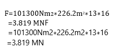
Using the force value above, four forces were applied on each part of the beam resulting in critical stress concentrations to improve load path clarity. However, the structure handled this well and supports might be necessary for the system to work. The study was conducted for titanium and aluminum. However, at the thickness prescribed 6061 T6 Aluminum alloy was chosen. The image below illustrates the study on the hexagon.
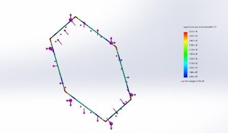
Figure 3: Hexagonal Sectioon of Bone Srtucture
The window got a makeover, the frame of the window is now welded to the end of the bone structure. The ISS style window on the habitat went through a small redesign in the latest iteration. It was newly redesigned using the Solid works weldments feature; meaning the new frame for the window is built into the bone structure. This redesign saved 164.88kgs.
Whipple Shield
The Whipple shield is the outermost layer of the lunar habitat that serves to protect the astronauts from micrometeorites. There have been several design alterations, and as of now, the Whipple shield consist of 6 layers of alternating Kevlar and Nextel in between two aluminum sheets with another 3 layers of the MLI (Multi-Layer Insulation) being attached to the base of the rear bumper. The Whipple shield subassembly is held together by an ANSI-metric M24x3.0 bolt and washer combo; there are tapped holes on the minimum sheets and through holes on the MLI, Kevlar, and Nextel layers. Each Whipple shields square section measures 400mm by 400mm. Figure 12 in the Appendix show the dimensions for the custom cylindrical fastener component.

Figure 5: Whipple Shiedl Design with Fasteners (Top and Side Views)
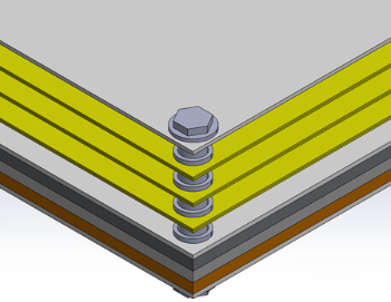
Figure 6: Whipple Shield With Materials Added
Pressure Wall
The second stress analysis was conducted on the pressure wall that rests on the inside of the bone structure. If the pressure wall can handle the force well enough, it would help alleviate the force acting on the bone structure. As a result, the thickness of 2.54mm and 25.4mm were compared. The 25.4mm worked better than expected. The images from the study are illustrated below.
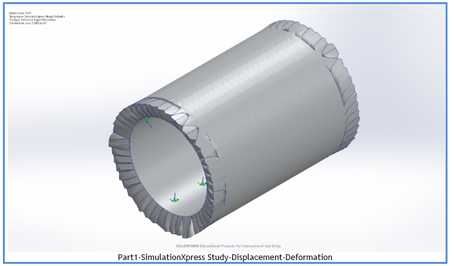
Figure 7: Displacement-Deformation results of Pressure Wall
The second study conducted compared Aluminum and Titanium. Titanium and Aluminum had similar stress and deflection parameters. However, Titanium weighed over 7000Kg. As a result, Aluminum was chosen as the ideal material for further analysis.
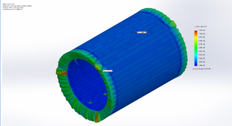
Figure 8: Stress Study Results of Pressure Wall
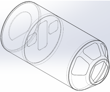
Figure 9: Hidden Line Isometric View of the Final Pressure Wall
AirLock Room
One of the most crucial aspects of the habitat is the integration of the airlock door into the design of the overall structure of the habitat. The depressurizing and the appropriate pressure values within the habitat, the material selection, dimensions, and CAD models, and details about the EVA (extravehicular activities). The habitat will consist of an airlock room where the astronauts will enter, get into their suits, depressurize the room, and exit the building through a pressurized door. The wall between the pressurized room and the natural habitat will consists of a suitport-airlock concept as well as an internal hatch door for the astronauts to move between the two rooms.

Figure 10: Suitport Airlock Concept
In preparation for the extravehicular activities, during the spacesuits donning and doffing, the suitport airlock environment’s pressure will be brought down to roughly 8.2 psia with about 34% O_2. The pressurized value within the environment is crucial for the limit pressure differential across the suits. Within the natural habitat, the normal air pressure should be held at 14.7 psia with the use of the ECLSS. With this design, there are multiple benefits for the sustainability and efficiency of a long-term design. There will be much less gas loss, decreased exposure of harmful radiation, dust and particles to the spacesuits and important systems within the habitat due to the rapid ingress and egress The fine dimensions of the airlock room, ingress and egress of the room, as well as the method of entering the space suits for EVAs has been selected based on the research studies that has been conducted for deep space travel. The overall diameter of the airlock room will be roughly 3.5 meters, higher than the previous 3.0 meters in order to accommodate the hatch door placed in between the two suit-ports. Within the airlock room, there will be roughly 11m^3 of internal volume space. To better assist the astronauts get into their suits easier, the suitports will be angled at a slight degree of roughly 20 degrees. Below is a visual representation of the fine dimensions of the initial airlock door and suit-ports.

Figure 11: Rear Entry Airlock Dimension
Scaled Prototype Description:
The bone structure was constructed by cutting, welding, and painting #3 3/8” rebar. The bone structure was constructed with the updated bone structure iteration including the new cross members. The pressure wall was constructed out of 24 gauge galvanized steel sheet metal. The sheet metal was plasma cut, rolled, and spot welded to create the desired cylindrical shape. The finished diameter was 13” designed to fit inside the bone structure. Figure 50 below shows the finished bone structure and pressure wall.
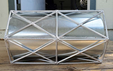
Figure 12: Pressure Wall and Bone Structure
The MLI was constructed by wrapping Aluminized Mylar around double reflective insulation. The mylar is intended to show the outer layer of the MLI and the DRI is intended to show the inner layers. The thickness of the insulation wrapping is around 10mm which is similar to the real thickness of the insulation aboard the full-scale prototype. Figure 51 below shows the finished and installed MLI.
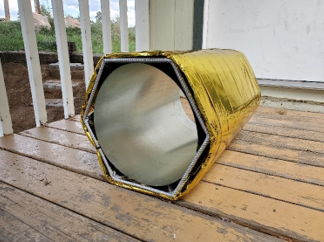
Figure 13: MLI
The floor was 3D printed using PLA at 15% infill. The model from the actual design was scaled down and slightly altered to fit the inside of the 13” diameter pressure wall. Figure 52 below shows the finished floor.
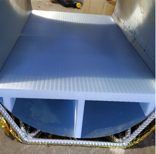
Figure 14: Concept Floor
The Whipple shields were constructed by cutting out 27 1ft X 8-inch sheets. Each of the sheets were stacked 3 high into the shield assembly using ¼-20 threaded bolts and washers. The sheets were spaced using stainless steel spacers. Figure 53 shows the finished Whipple shield assembly.
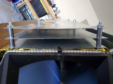
Figure 15: Whipple Shield
The window was 3D printed using PLA and a 15% infill and glued together using superglue. The window was specially designed for the prototype to interface with one of the flat sides and attach to the frame. Figure 54 shows the fully assembled and installed window.
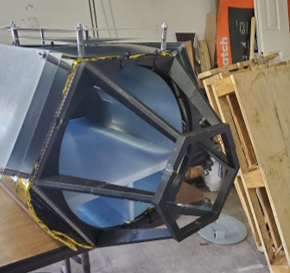
Figure 16: Window Assembly