Gallery
Trip to SunTrac

This a 6 foot solar panel that SunTrac owns.

The director of Engineering in SunTrac explaining how the solar panels work.

Explaining the pros and cons to using this jig.

The director of Engineering explaining the customer requirements of designing the jig.
CAD Assembly
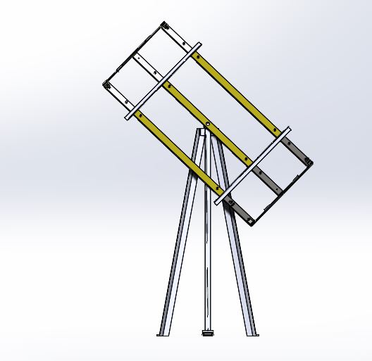
Front view
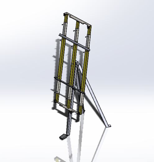
The first CAD design.
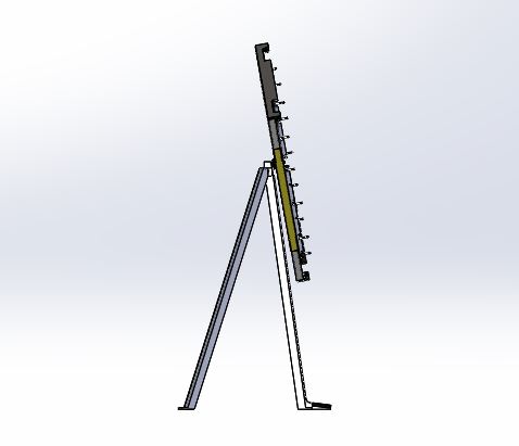
Side View
First Prototype
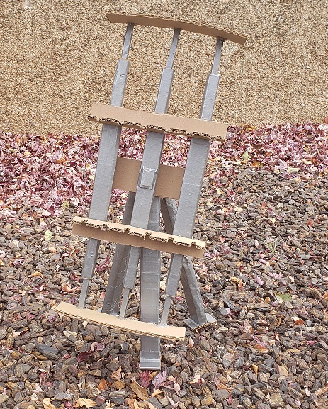
The first low fidelity prototype that contains the physical characteristics of the jig.
Subsystem 1 Protoype: Extending Square Tubes
This subsystem makes up the frame of the jig which allows it to adjust to three different sizes.
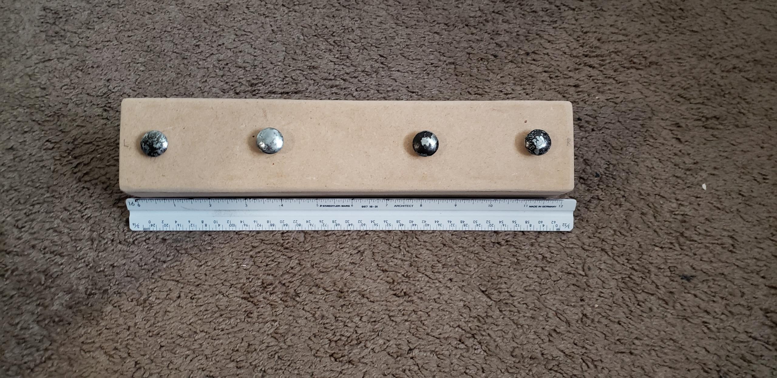
The unextended tube which will be used to weld 4 foot copper manifolds.
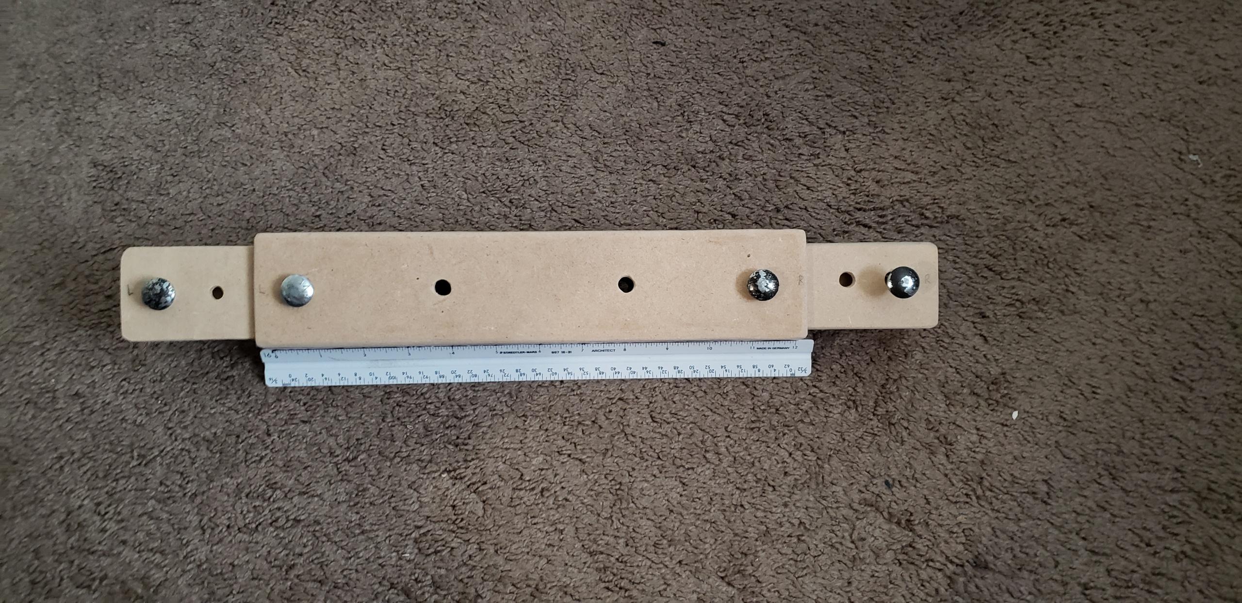
When it is extended once on each side, it will fit 6 foot copper manifolds.
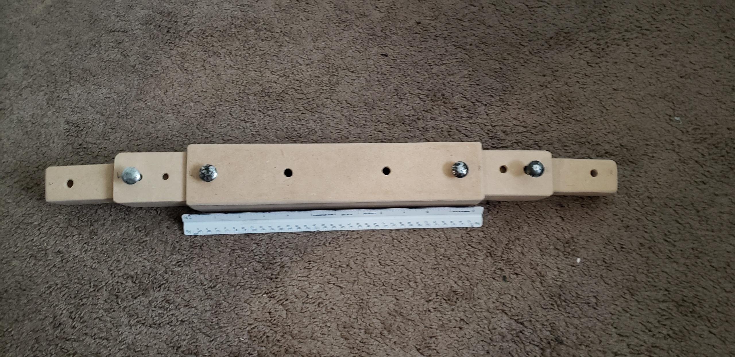
When it is extended all the way, it will fit 8 foot copper manifolds.
Subsystem 2 Protoype: Rotating and Locking Mechanism
This subsystem allows the jig to rotate and lock by utilizing a foot pedal and a gear. When the pedal is pressed it will release the gear thus allowing it to rotate.
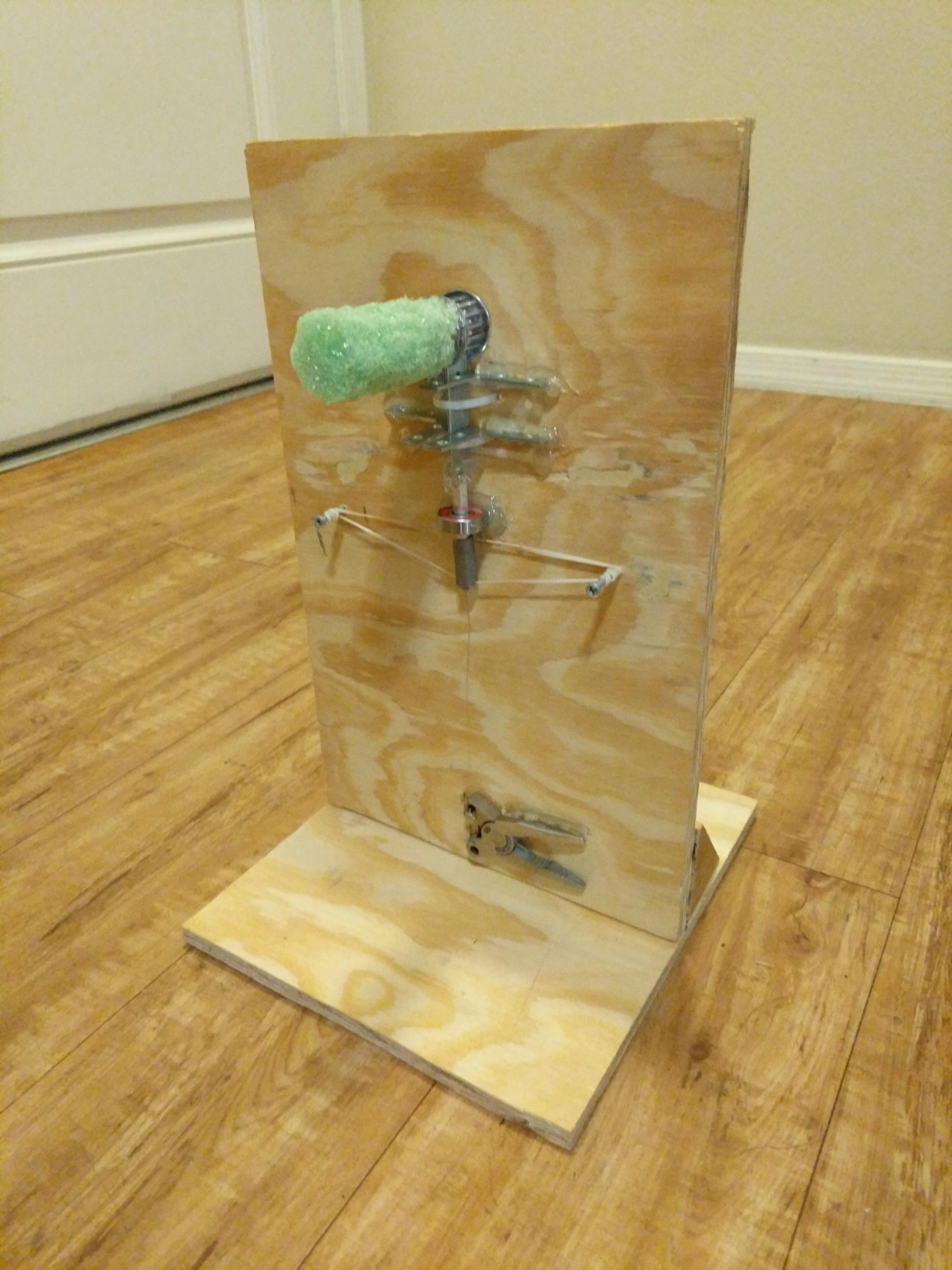
The clamp is pressed which applies tension on the cord which pulls the lock down thus releasing the gear.
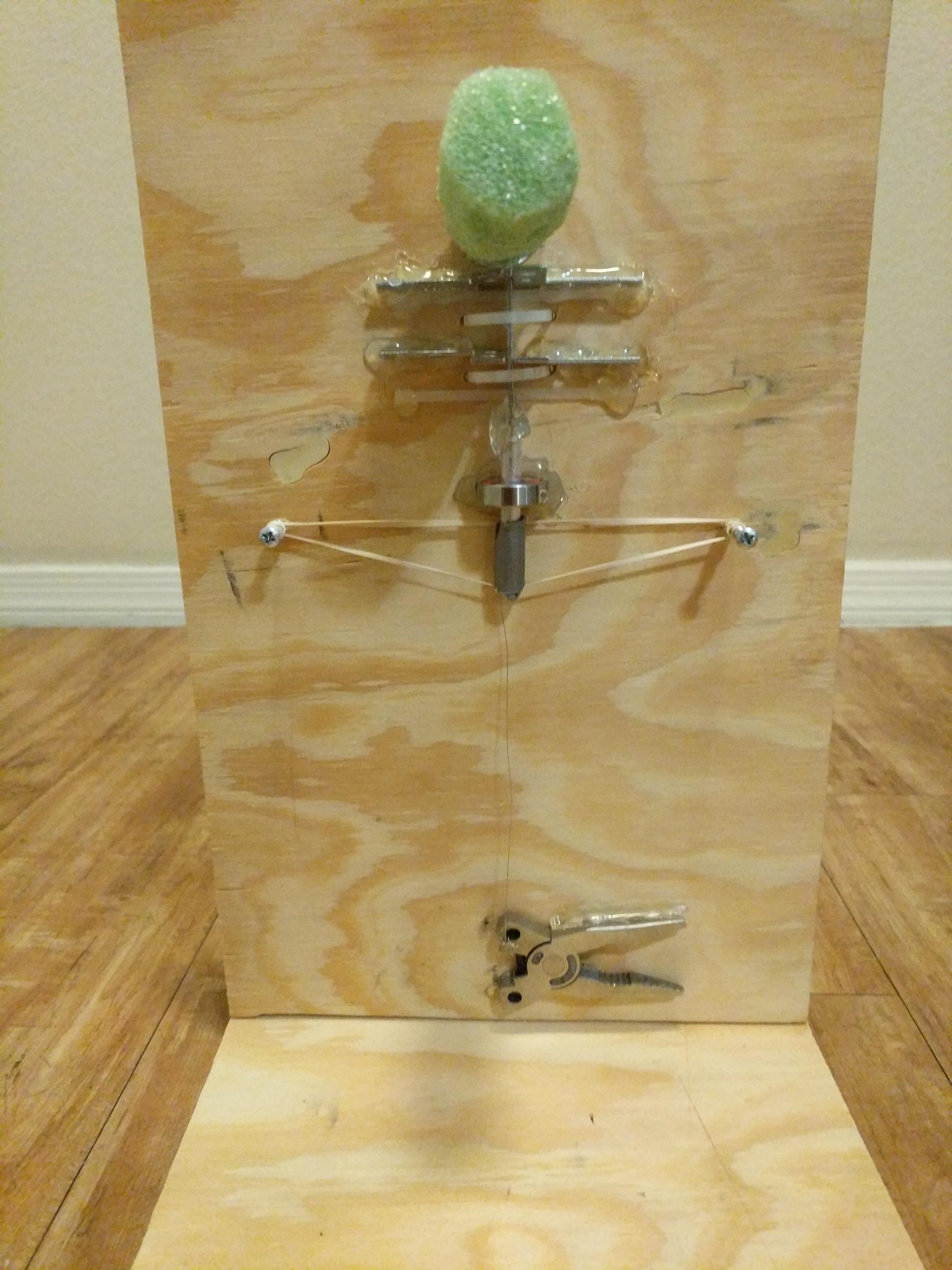
The green cylinder on the top represents the jig and the clamp on the bottom is the foot pedal.
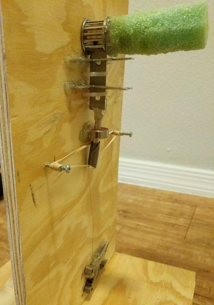
Side view detailing the gear and lock assembly.
Subsystem 3 Protoype: Power Screw Lock
This subsystem locks the horizontal pipes while they are being welded.
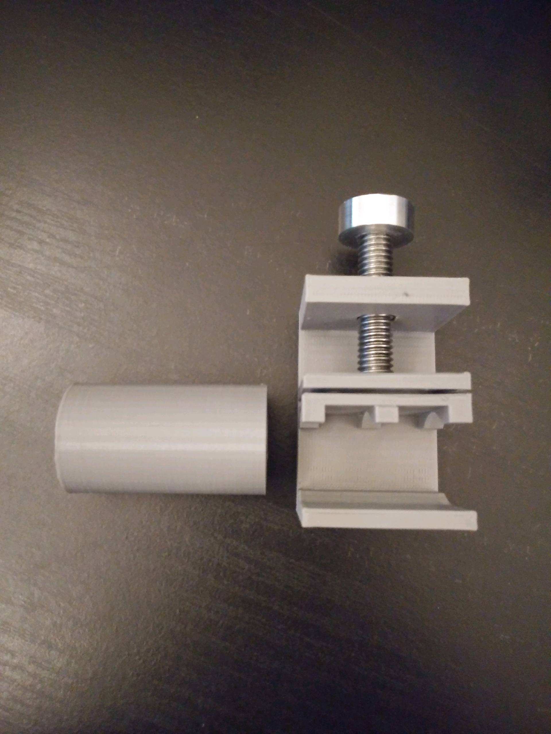
The pipe slides through the bracket and the power screw locks it by applying pressure from the top plate.
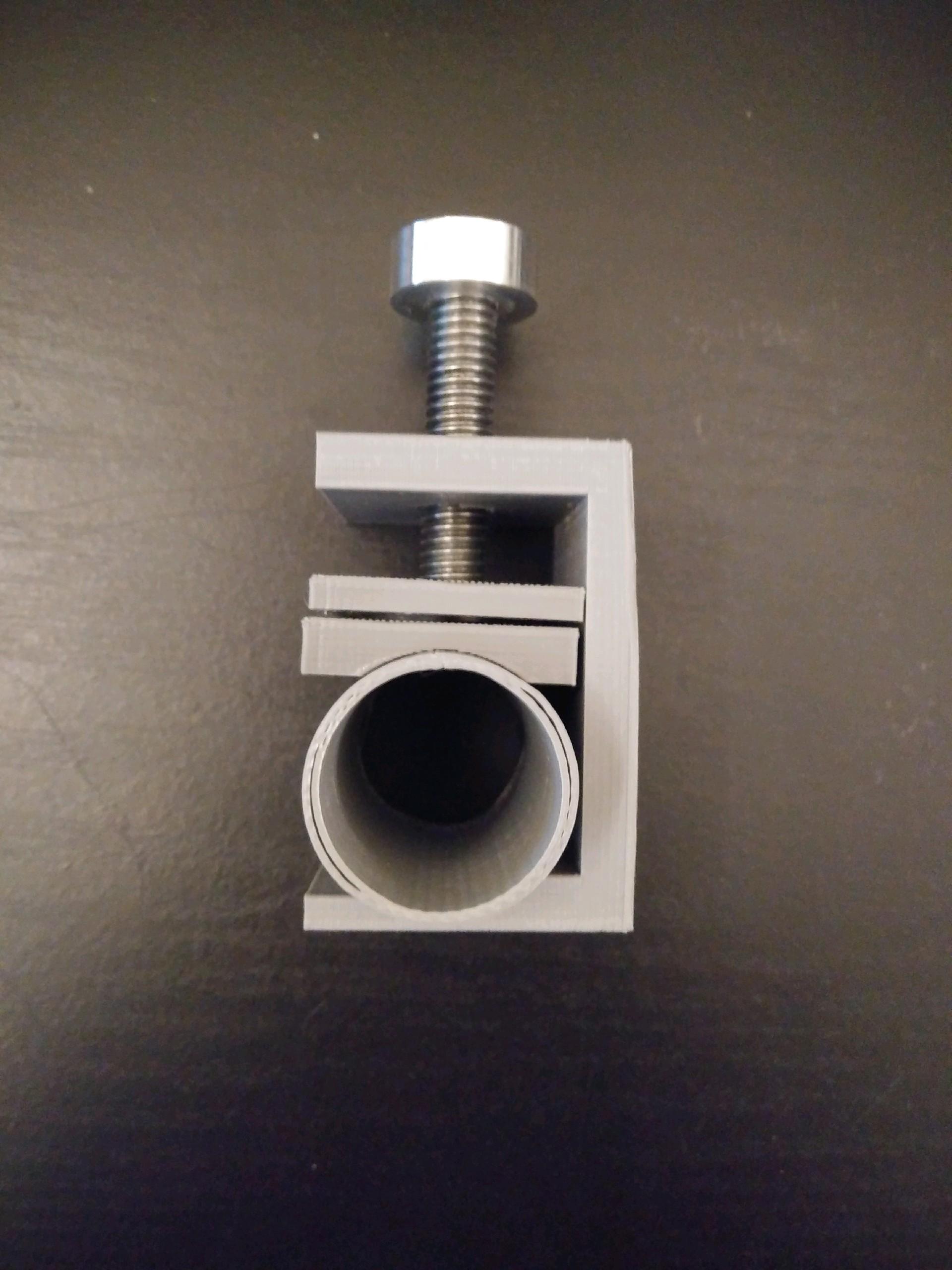
Side view detailing the subsystem when the pipe is locked in place.
Working Area Close Up
A closeup of the working area on the Jig's face.
Updated CAD Pictures
The following pictures show the updated CAD systems on the stand.
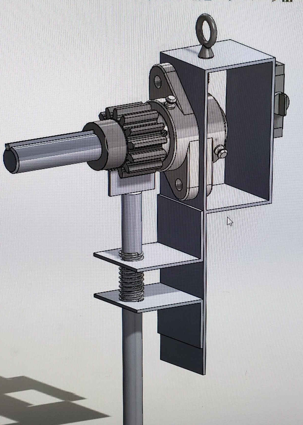
This is the locking mechanism on the jig.
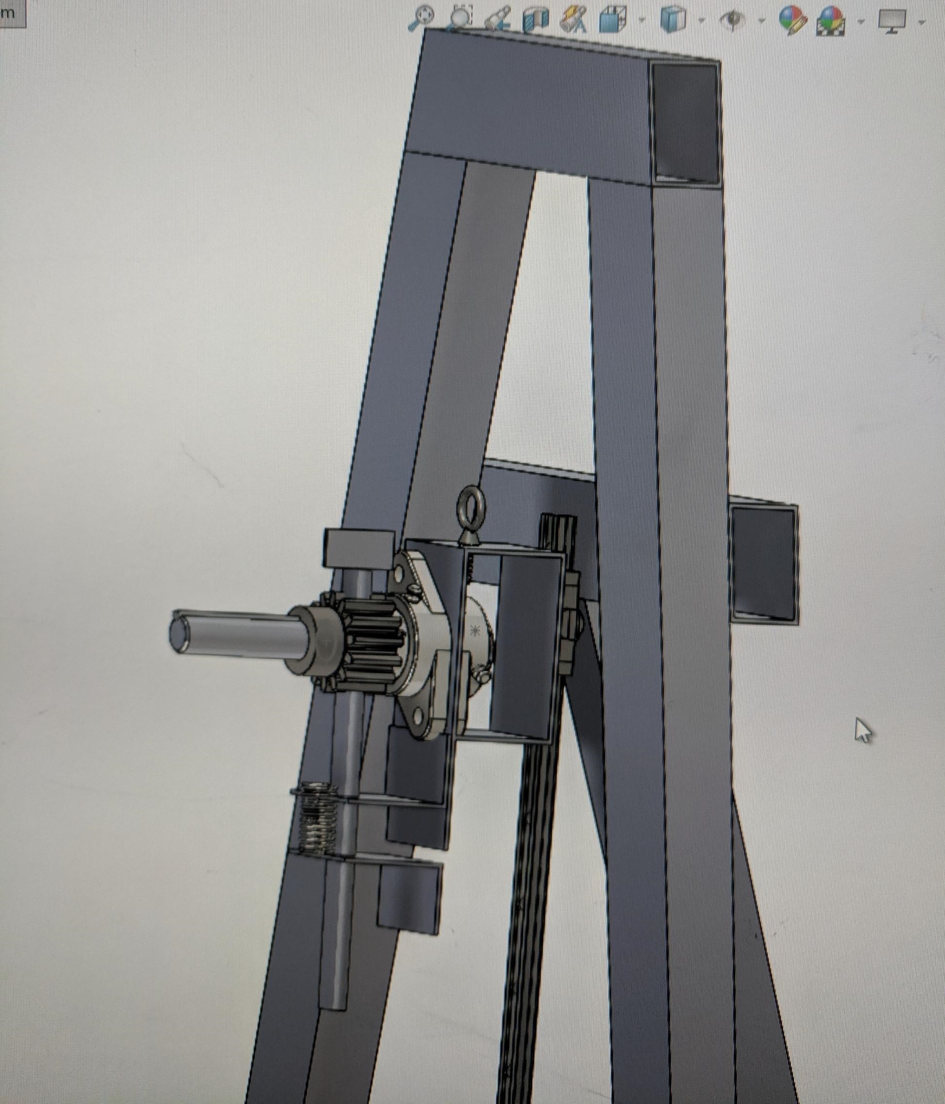
Back view of the stand.
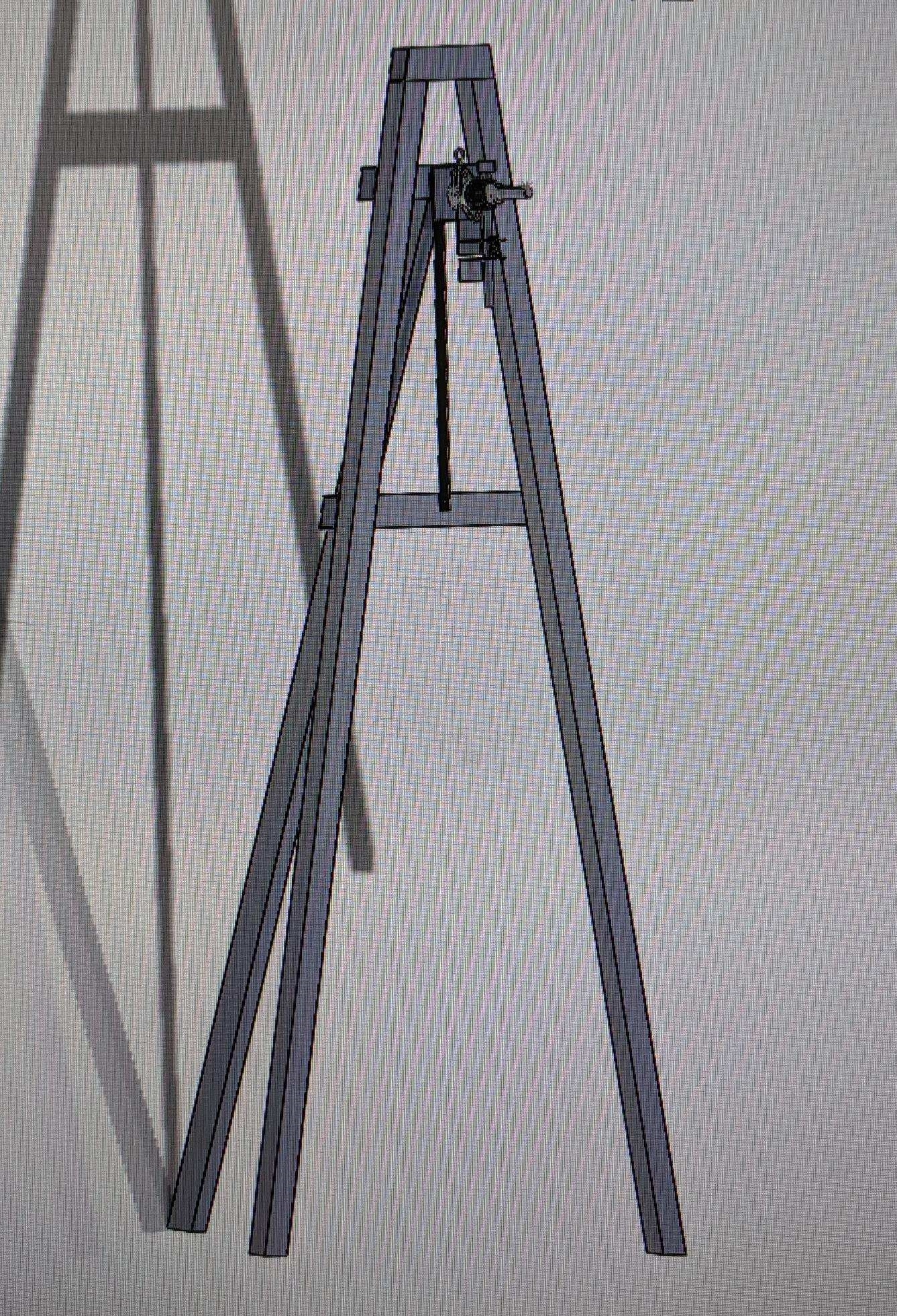
Updated design of the stand.
Manufacturing Process
Cutting the angles of the jig frame.
Drilling Holes.
Consulting a supervisor.
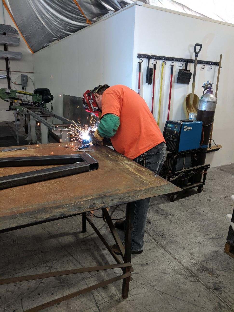
Welding the jig.
Final State of the Jig
The manufacturing process could not be completed due to the virus outbreak. The two pictures below represent the jig at its final manufacturing stage before the outbreak.
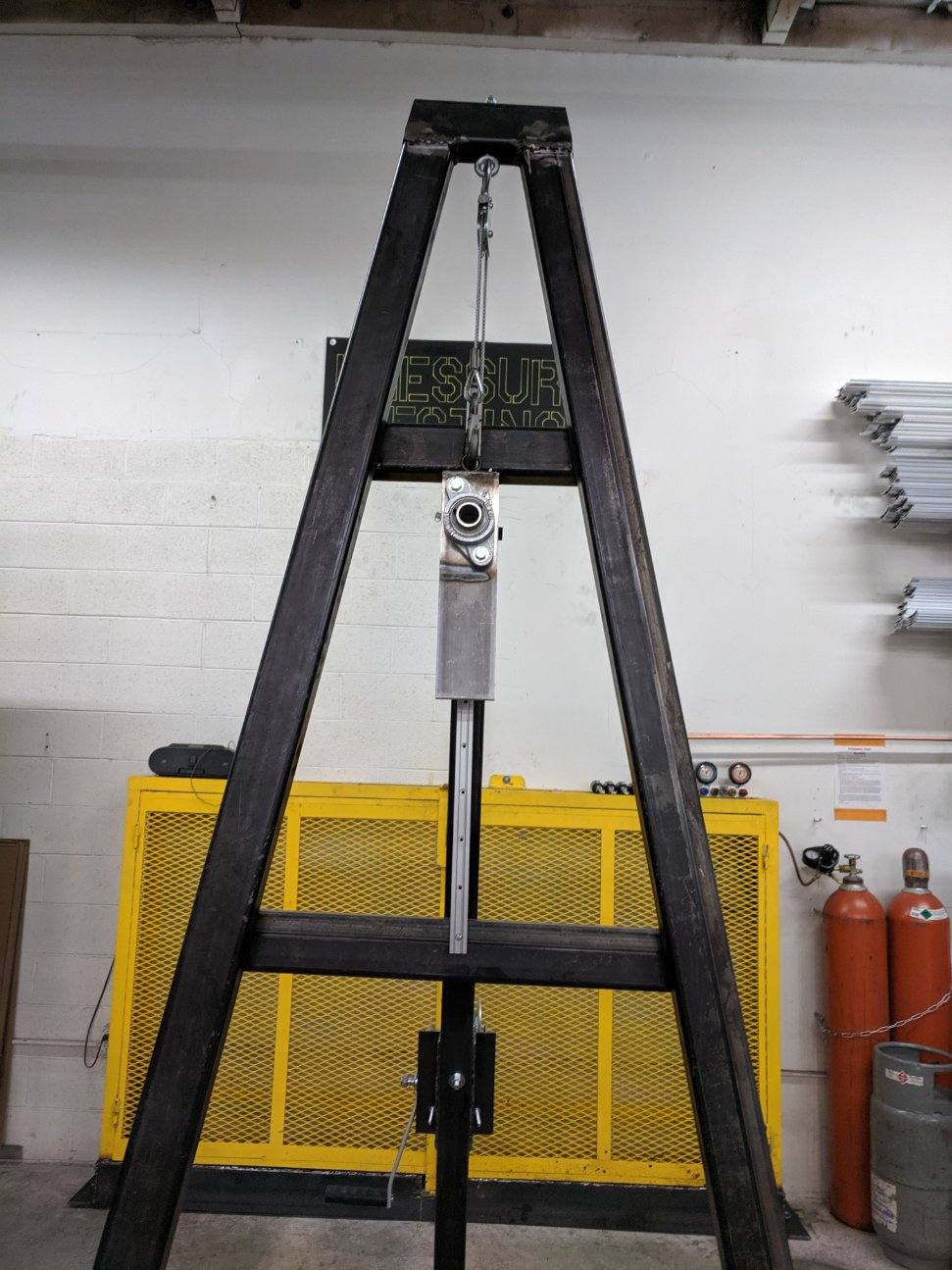
Front View of the Jig.
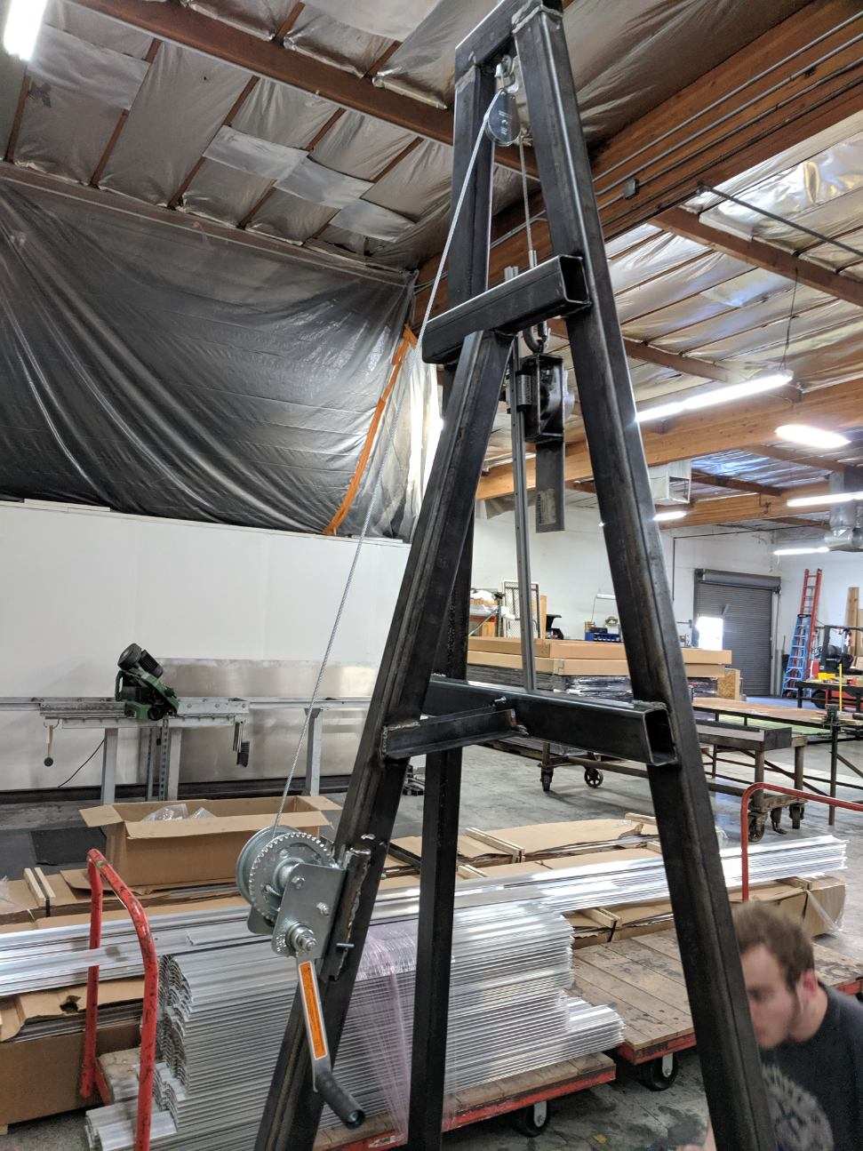
Side View of the Jig.
Team Selfie
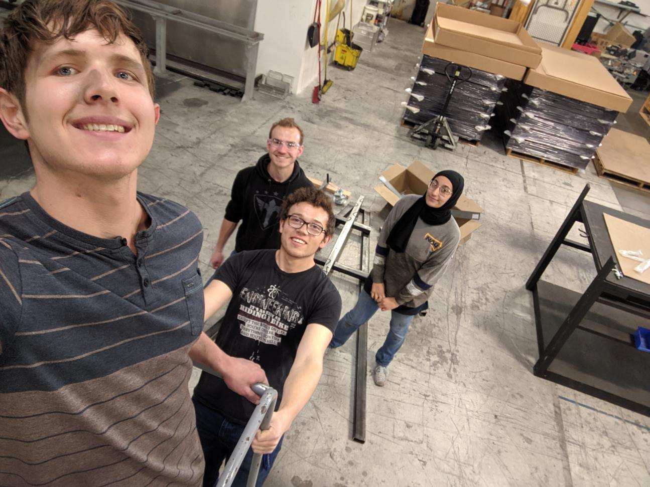
Last Selfie Taken in SunTrac Facility.