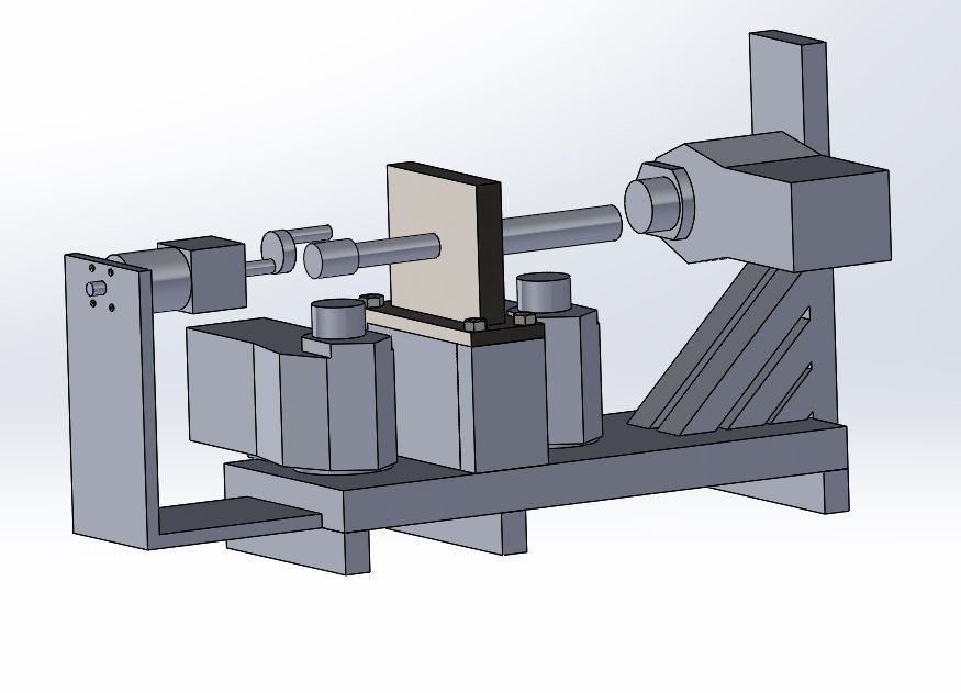
Final CAD Model
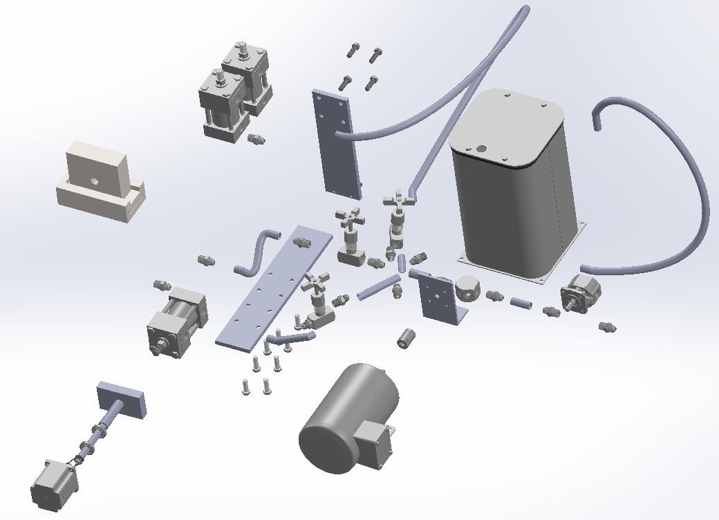
Exploded View of the CAD Model
Images of our first Prototype
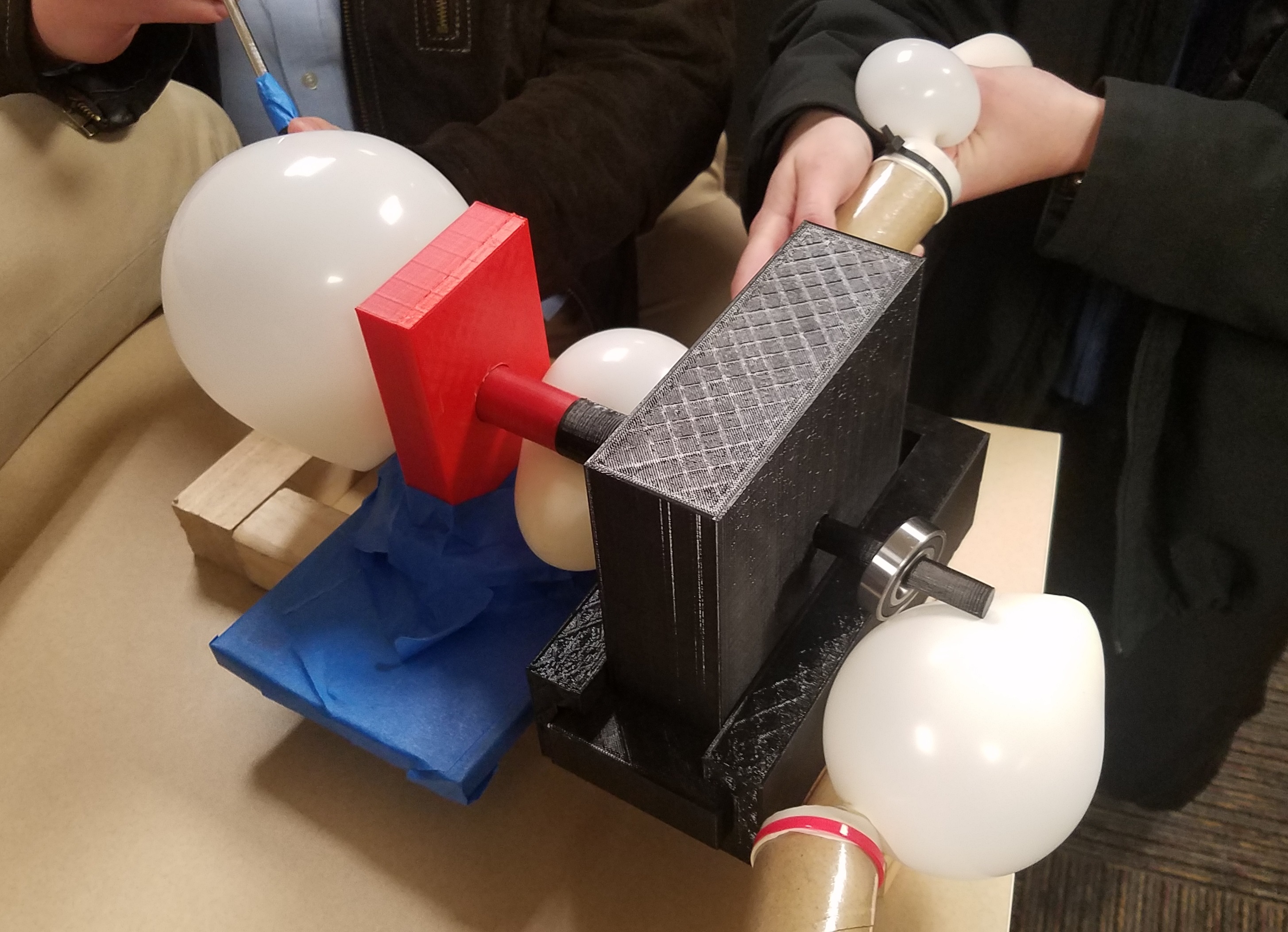
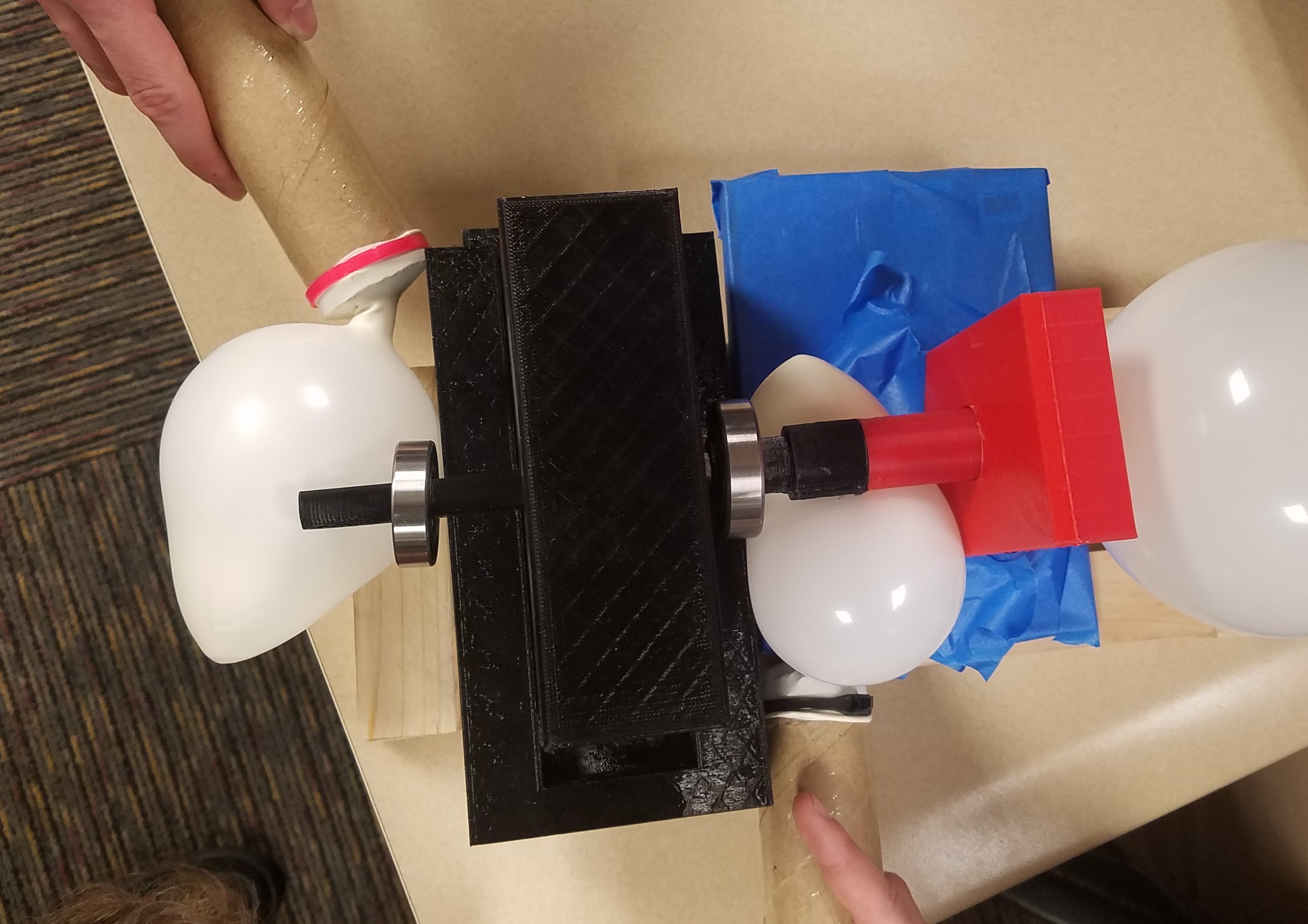
A prototype was 3D printed to illustrate how the team planned on applying the loads and securing the bearings. The balloons simulate a hydraulic system.
Images of the Build
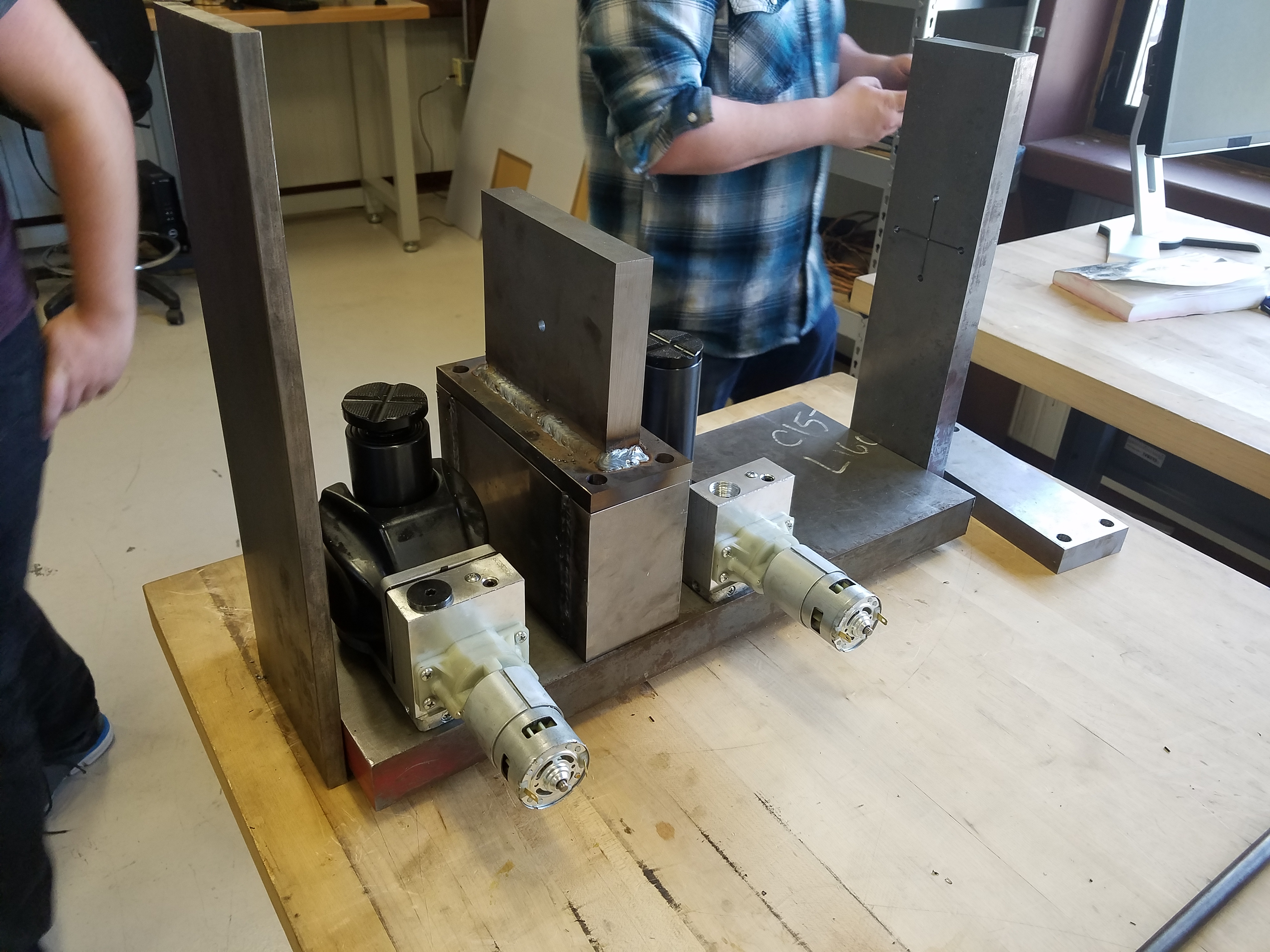
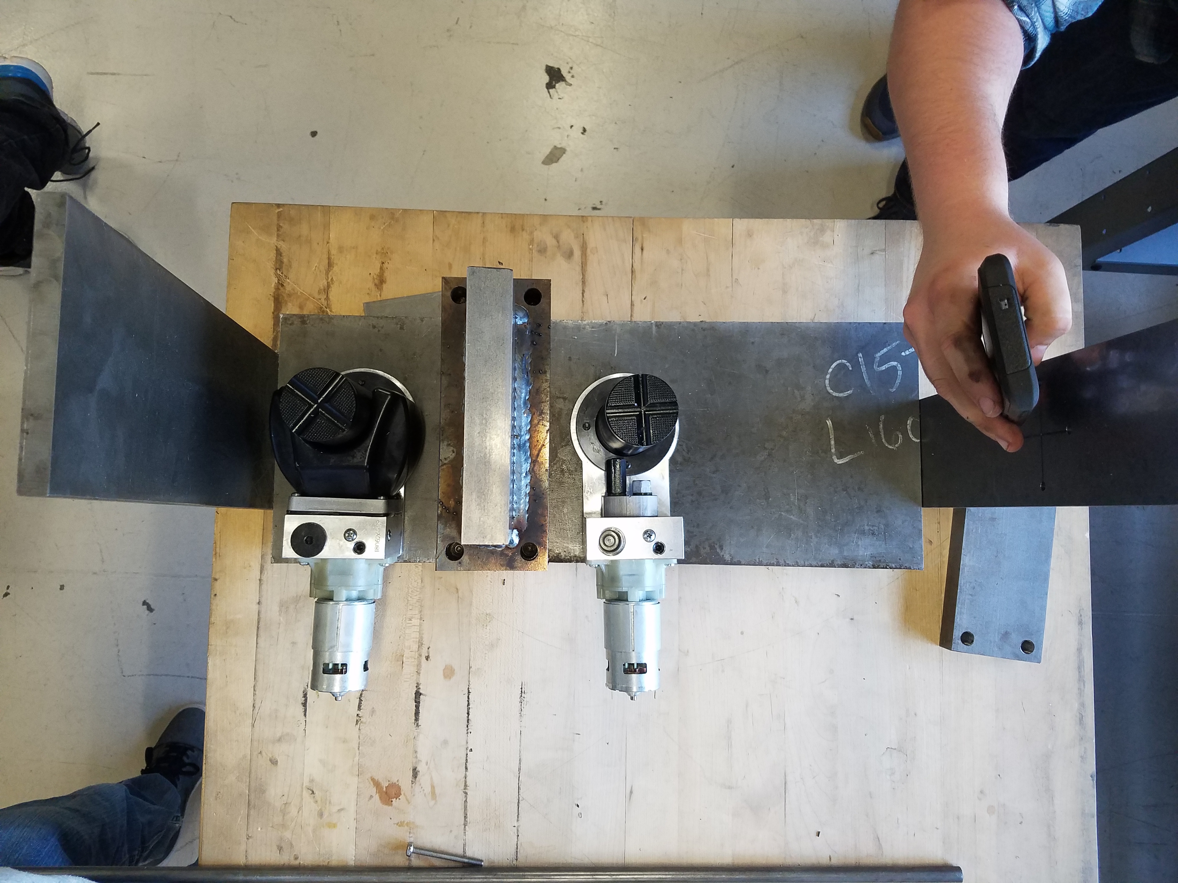
Most of the steel is cut and is ready to be welded to the frame.
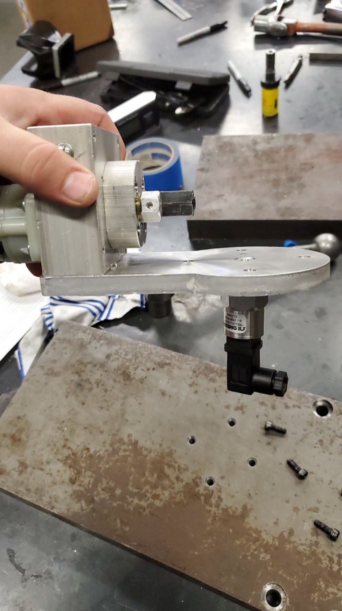
Holes were drilled out the bottom of the jacks and threaded so that a pressure transduer could read the pressure of the hydraulic fluid.
This is then used to find the force the jack is imparting.
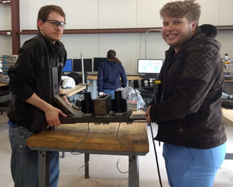
Nestor and Barek prove that the fixture can be moved by two people.
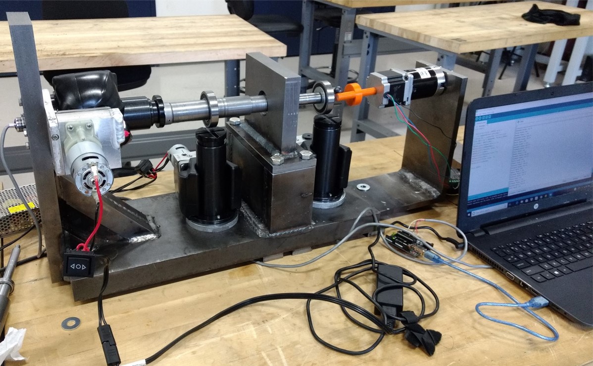
The final assembly. Jacks apply forced to the shaft radially and axially. Pressure transducers relay that information to an Arduino system which diplays on the computer.
A stepper motor is controlled by Arduino and rotates the shaft. The system has four different sized bearing housings which are easily interchangable allowing the user to test multiple bearings.