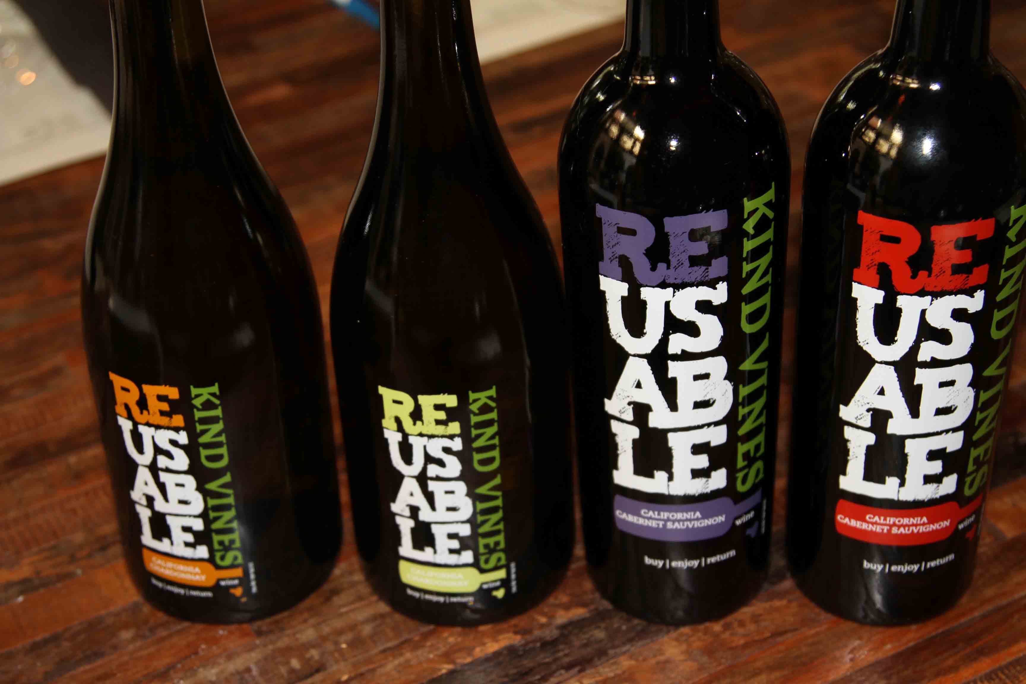
Design Layout Drawings
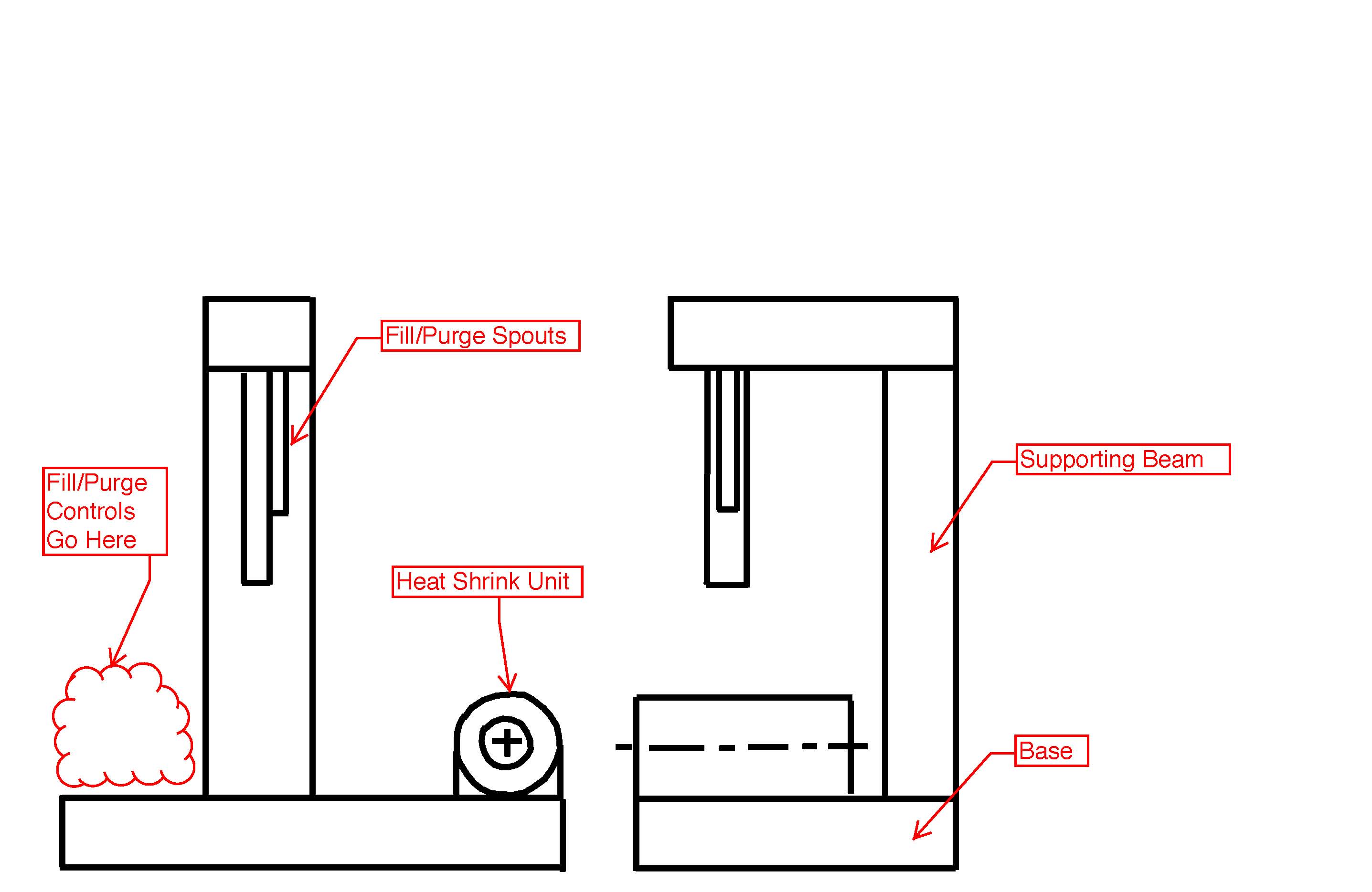
The figure above shows the general layout that has been determined as per discussions between the project team and the client. The area within the “cloud” is where the controls, whether manual or electrical, will be placed. The heat shrink applicator unit will be located on the right side of the machine and the fill/purge spouts, whichever design is chosen, will be attached over where the bottles are to be filled. The location of the controls and heat shrink unit can be switched if necessary. As the general layout has already been determined and the design of the supporting elements of the filler (base, supporting beam and filling beam) will be adapted to meet the needs and dimensions of the choice of fill/purge controls/spout and heat shrink unit.
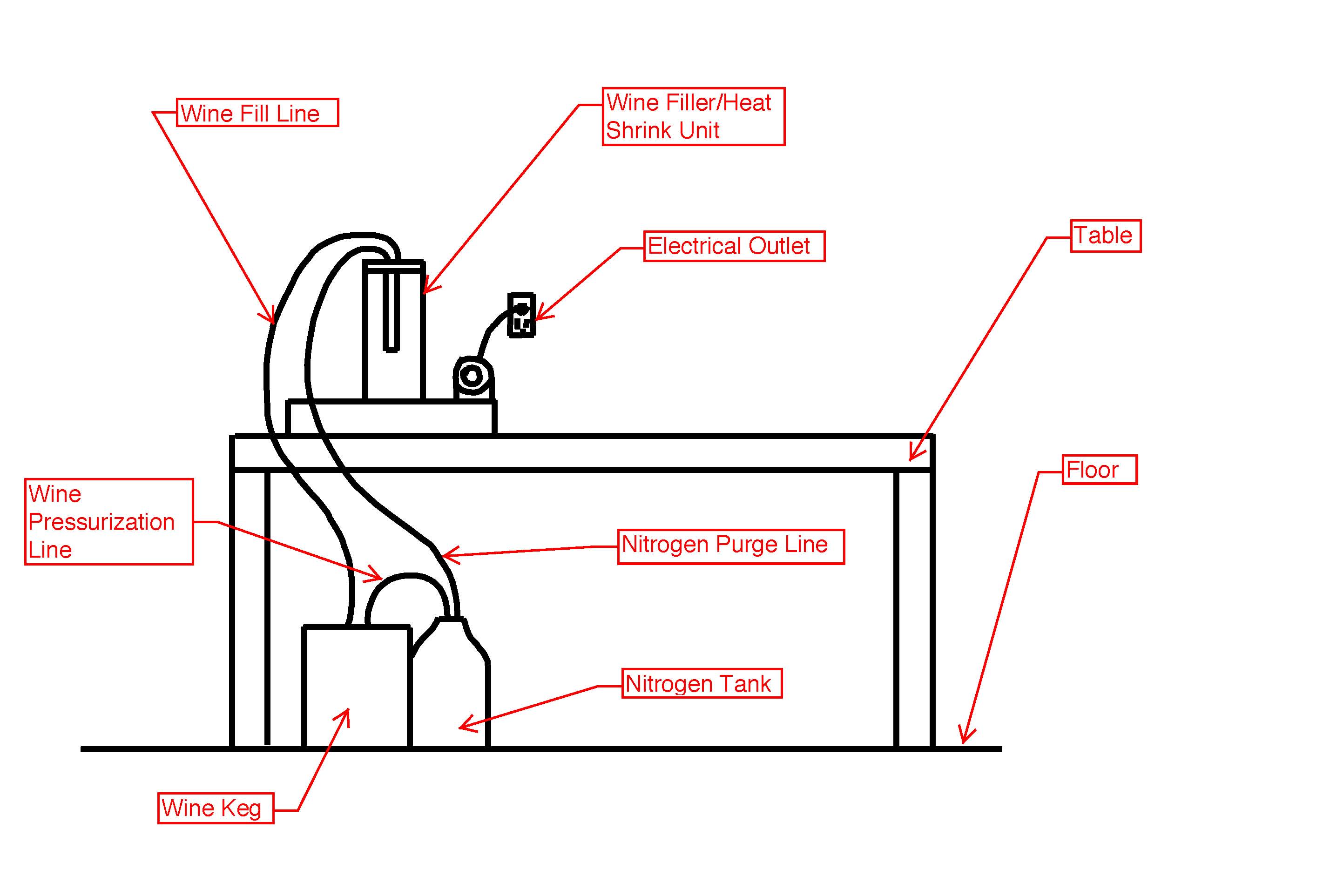
The figure above shows the way in which the client intends for the product to be used in a restaurant. The wine filler/heat shrink unit will be placed on a table or other free area in the back of a restaurant. Underneath the filler/heater will be a pressurized nitrogen tank and a wine keg. The nitrogen tank will be used to pressurize the wine keg, for wine disbursement to the filler, and for the bottle purging operation. The heat shrink applicator and potentially the valves, if a solenoid actuated option is chosen, will need to be connected to a standard 120V AC electrical outlet.
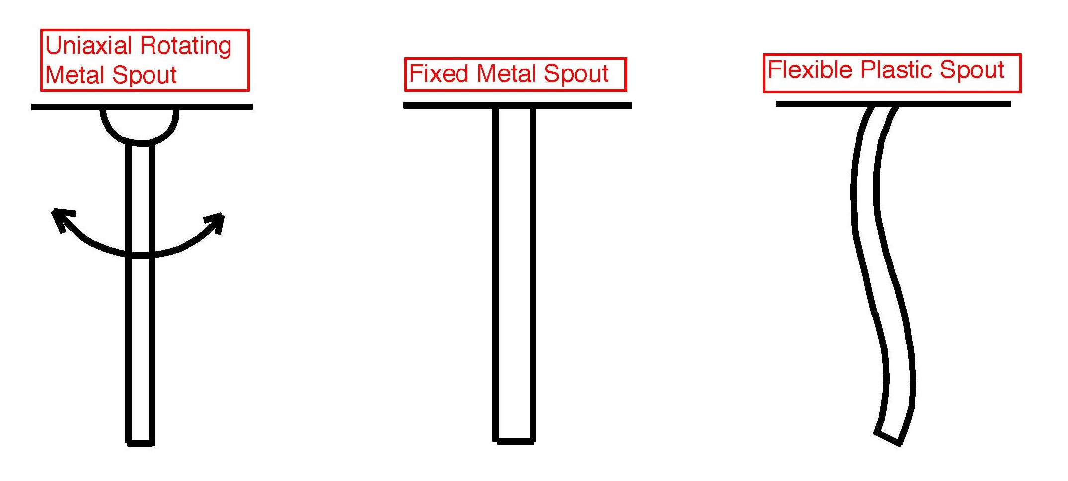
The figure above shows the three spout designs to be chosen from. The uniaxial rotating metal spout will be able to rotate either towards or away from the filler unit so that the filler could be inserted into a bottle and then the bottle/filler be rotated and placed onto the filler base. The advantage of this spout design is that it allows for an adaptive spout system that allows for flexibility in the design of the base. The rigid metal spout would be fixed at a particular angle and would have the advantage of costing less than the rotating spout but also, due to the lack of moving parts, have the potential to be a more reliable system. The flexible plastic spout combines the positive attributes of the two previously mentioned designs. It also has the advantage of costing less than the rigid metal spout but also having the flexibility of design and operator use as is present in the rotating metal spout.
Solenoid Actuated Valve
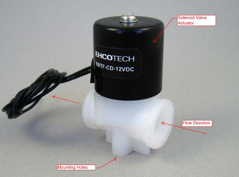
The figure above shows a solenoid-actuated valve that could be used to control the dispense time for the wine as well as the nitrogen purge, with separate valves for each operation. It would be controlled by a timing circuit that would dictate how long the valve should open for, thus dispensing the proper amount of wine/nitrogen.
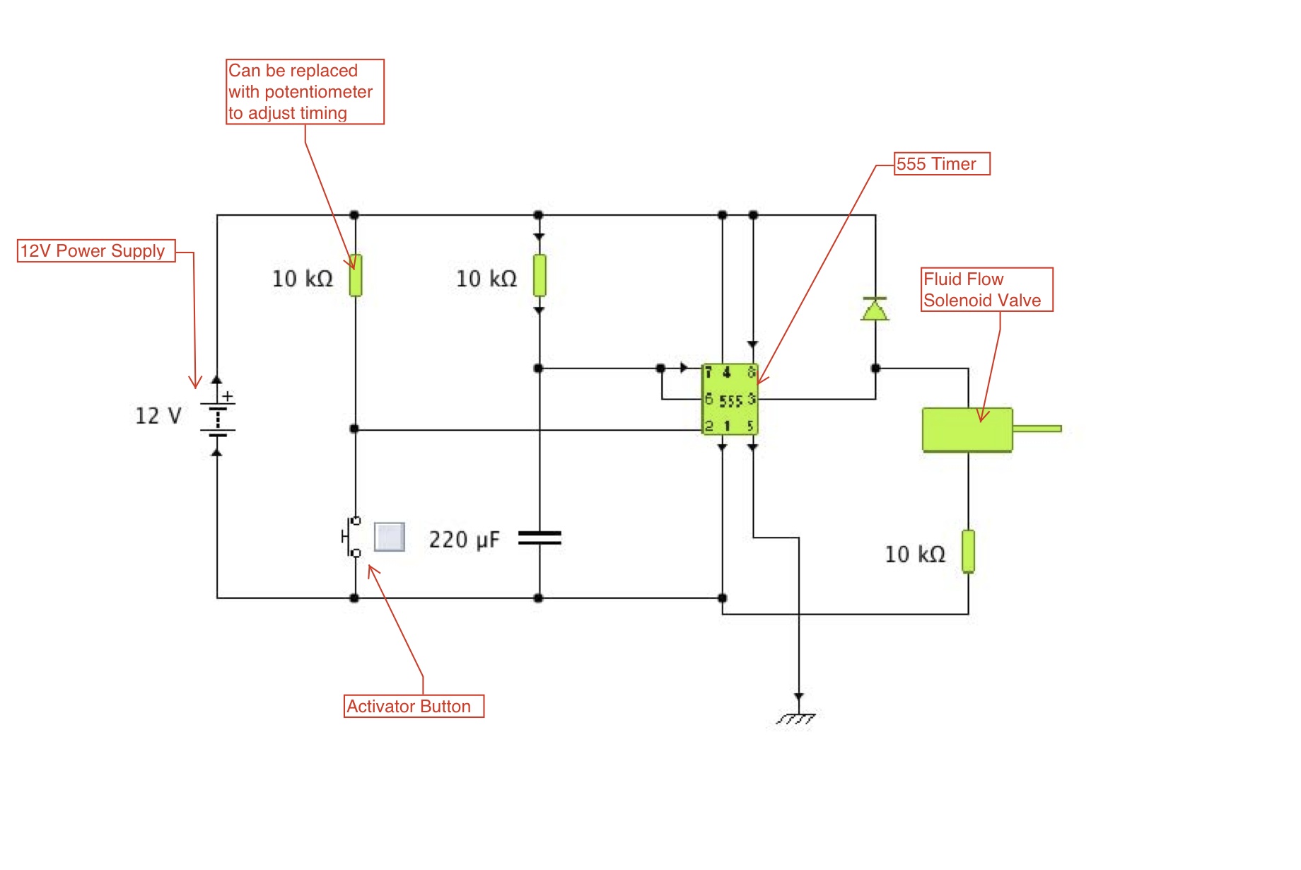
The figure above shows the proposed circuit to be used with the solenoid-actuated valve. The farthest left resistor can be replaced with a potentiometer to allow for fine adjustment of the circuit timing as well as the other resistors being changed accommodating for a certain time of actuation. It would be powered by a 12V DC power supply; the same one the actuated valves will be operated on.
Heat Shrink Element
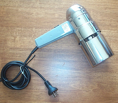
The figure above shows a hand held heat shrink unit used to shrink the heat seal placed around the top of the filled and corked wine bottle. The advantage of the unit being hand held is that the operator is not constrained to orienting the wine bottle in a specific direction, which would help if the unit was located in a spacially restrictive environment. The disadvantage of this design is that, since it is not stationary, the operator has a higher chance of burning themselves on the exposed metal.
