Team H2Oleum used a combination of Gas Injection System and Chemical Coagulation as the overall system designed to separate the emulsified oil from industrial wastewater. The first stage of our design to inject the solution with a chemical coagulant; the coagulant will increase the surface area of the emulsified oil particles. The second stage will undergo dissolved air filtration, which will increase the efficiency of the separation by joining the coagulated oil particles to air bubbles so that the particles rise to the surface of the water. The flow of the emulsion will begin with the storage tank and travel from left to right.
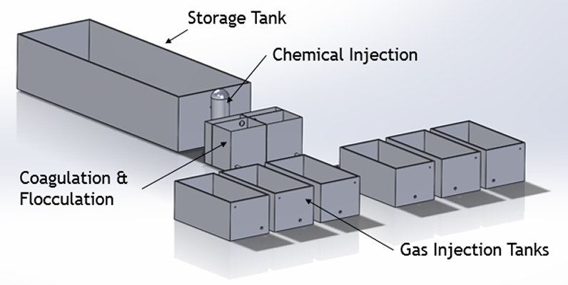
In the full scale design, a 16,000 gallon storage tank will receive the emulsion from the upper left corner of the tank where it will accommodate flows of emulsion up to 130GPM for 2 hours.
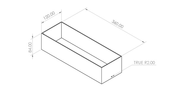
The dimensions of the full scale storage tank are: 10 ft (120 in.) width × 30 ft.(360 in.) length ×7 ft.(84 in.) height. The emulsion will be passed to the next stage through the hole at the bottom of the tank which has a radius of 2 inches.
The dry chemical injection system is used to introduce a chemical coagulant into the emulsion. The addition of the chemical destabilizes the emulsified feed solution by causing the oil particles to coalesce and form flocculent masses as a cloud at the surface of the water. The chemical coagulant will be introduced in-line with the feed solution for optimal contact time. The chemical coagulant that will be Ferric sulfate with a dosage of 30 mg/L.
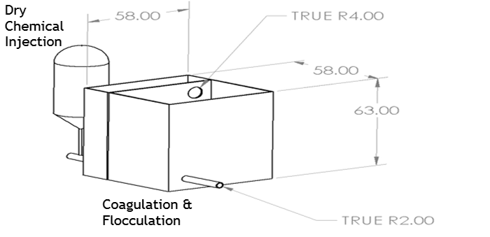
The CFS is divided into two sections for rapid mixing and slow mixing.
First rapid mixing will occur at over 200 RPM in the first section of the tank with a retention time of 2 minutes to allow for an even dispersal of the dry chemical throughout the emulsion. Rapid mixing also allows the oil particles and other mineral contaminants to destabilize faster as they mix with the chemical coagulant.
The second section of the CFS system involves a transition to slow mixing under 20 RPM for a 5 minute retention time. After completing the retention time, the oil particles will have increased in size and can be classified as part of the dispersed phase range. Valves will open that allow the solution to pass into the tanks for the gas injection system.
From each chemical coagulation tank, the emulsion will pass into 3 separate gas injection tanks. Under overload operations, when the storage tank receives flow over 100 GPM, both chemical coagulation tanks and all six gas injection tanks will be used. Under normal operation, the 1st gas injection tank will be ready for more emulsion by the time the 3rd gas injection tank is halfway full.
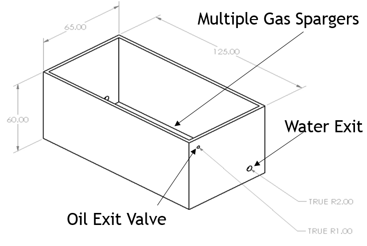
Each gas injection tank will use multiple gas spargers to dissolve nitrogen compressed gas into the oil emulsion; the porous gas spargers will allow the dissolved gas to release tiny gas bubbles (2 micron diameter) which create more surface area throughout the emulsion.
More surface area translates to further destabilization in the dispersed oil particles which causes them to coalesce into other oil particles. As the oil particles combine, they will increase in size which will effectively increase their rise rate allowing the oil to accumulate on the surface of the water.
A thick oil layer is achieved by draining the water from each tank but leaving the previous oil layer intact. After multiple batches, the oil layer on the surface of the water will accumulate until the oil layer is thick enough to collect; a valve placed at the top of the gas injection tanks will allow the on-site operator to collect the oil that is above the water interface.
CLICK HERE FOR MORE INFORMATION ABOUT THE PROJECT
