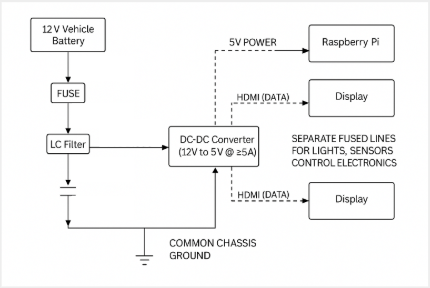
Power Conversion Block Diagram
Controller Platform
The driver display and high-level control logic are planned to run on a Raspberry Pi using Linux as the operating system. The graphical interface will be developed in Python using Qt, giving the team flexibility to prototype different layouts while still running on embedded hardware.
- Real-time telemetry data displayed to the driver.
- Ability to load rasterized track maps when available.
- Color alerts for warnings and errors to make issues easy to spot.
- Communication with vehicle subsystems using a standard serial interface (UART).
Digital Dash Concept
The current concept uses two screens so that critical information can stay visible while secondary information is available when needed.
- Tachometer, speedometer, and other key engine or vehicle values.
- Any active errors or warnings highlighted in color.
- Live map view with vehicle location when GPS data and a track map are available.
Hardware Implementation
The wiring harness and component placement follow the design documented in the wiring diagrams, with attention to strain relief, service loops, and separation from high-heat or moving mechanical parts. Automotive-grade wire, fusing, and connectors are used where possible to improve reliability.
- Mounting locations chosen to minimize vibration and potential impact damage.
- Harness routing away from sharp edges, moving linkages, and hot engine components.
- Use of loom, grommets, and strain relief where the harness passes through panels or tight spaces.
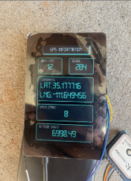
Previous Dashboard Example
The image below shows a dashboard and GPS display prototype built by a previous Baja team. It is included as a reference for packaging and readability; the current electrical design will develop its own layout using the Raspberry Pi and displays described above.