
The following section offers an in-depth look at various essential electrical components used in the project's design. Throughout the course of the project, the team will enhance and reiterate the initial prototypes, ensuring that each iteration aligns with our evolving system requirements and contributes to improved overall system performance. As the project continues, this page will be regularly updated to reflect any circuit modifications, improvements, and any integration of new components, all contributing to the successful realization of the team's main objectives.
AC/DC Rectifier: An AC to DC rectifier is crucial to the system to convert generated AC voltage to DC, as the competition requires the voltage to be DC at the PCC and various system components require DC. The team acquired one design that is off-the-shelf, an IC that utilizes six diodes [Figure 1]. The team has been actively using a home-made circuit that also utilized six diodes for rectification [Figure 2].
DC/DC Boost Converter: A DC/DC boost converter is used to ensure a steady and usable voltage for all system components. The boost converter [Figure 3] features an 8A, 100 μH toroidal inductor, IRFZ44N MOSFET, and a 47 μF capacitor for voltage smoothing. By adjusting the MOSFET's duty cycle, the output voltage can be controlled to meet different system voltage requirements.
DC/DC Buck-Boost Converter: The buck-boost converter can step up and step down an input voltage. The selected module can produce a steady output voltage that can be changed manually by adjusting the potentiometer on board the module. This converter is crucial to the system as it keeps a varying input voltage within a certain acceptable output voltage range (7-12 VDC) for the Arduino to remain powered on and within its healthy range.
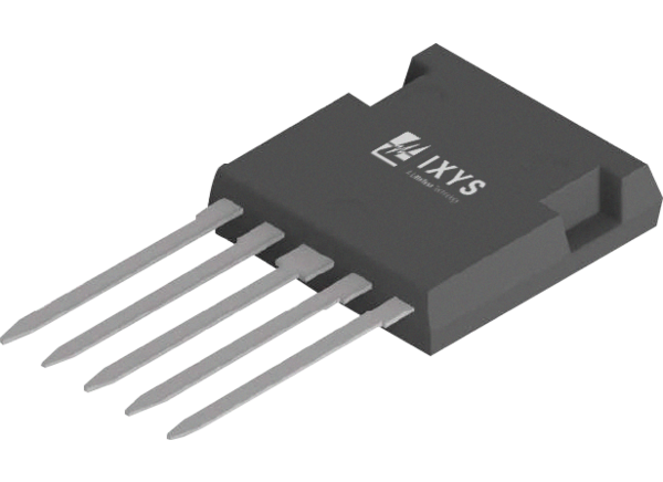
[Figure 1: IXYS DPF30U200FC Rectifier]
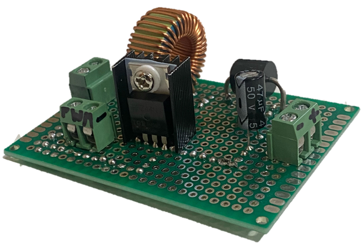
[Figure 3: DC Boost Converter Prototype]

[Figure 4: DC Buck-Boost Converter Module]
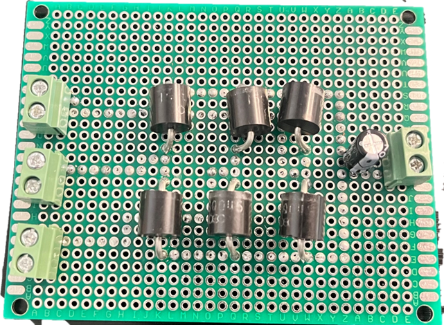
[Figure 2: Team Made 3-Phase Rectifier]
System Controls: An Arduino Mega 2560 is used for various controls such as turbine functions including pitching and braking. The Arduino Uno R3 also has a low operating voltage with an absolute minimum of 5V. In addition to controlling motors and actuators, the microcontroller manages the closed-loop control system of the DC/DC boost converter, which offers automatic regulation of the output voltage. Through use of voltage and current sensors the Arduino also controls the switching for the diverter load.
Closed-Loop Control: The DC/DC Boost Converter utilizes a closed-loop control system to regulate the output voltage at 20V by adjusting the MOSFET’s duty cycle through a PWM signal from the Arduino microcontroller. The output voltage is measured using a voltage divider, while the current is measured by an ACS712 hall effect sensor. The duty cycle is adjusted based on the error between the target voltage and the measured voltage, using a duty cycle range between 0% and 85% to ensure stable operation.
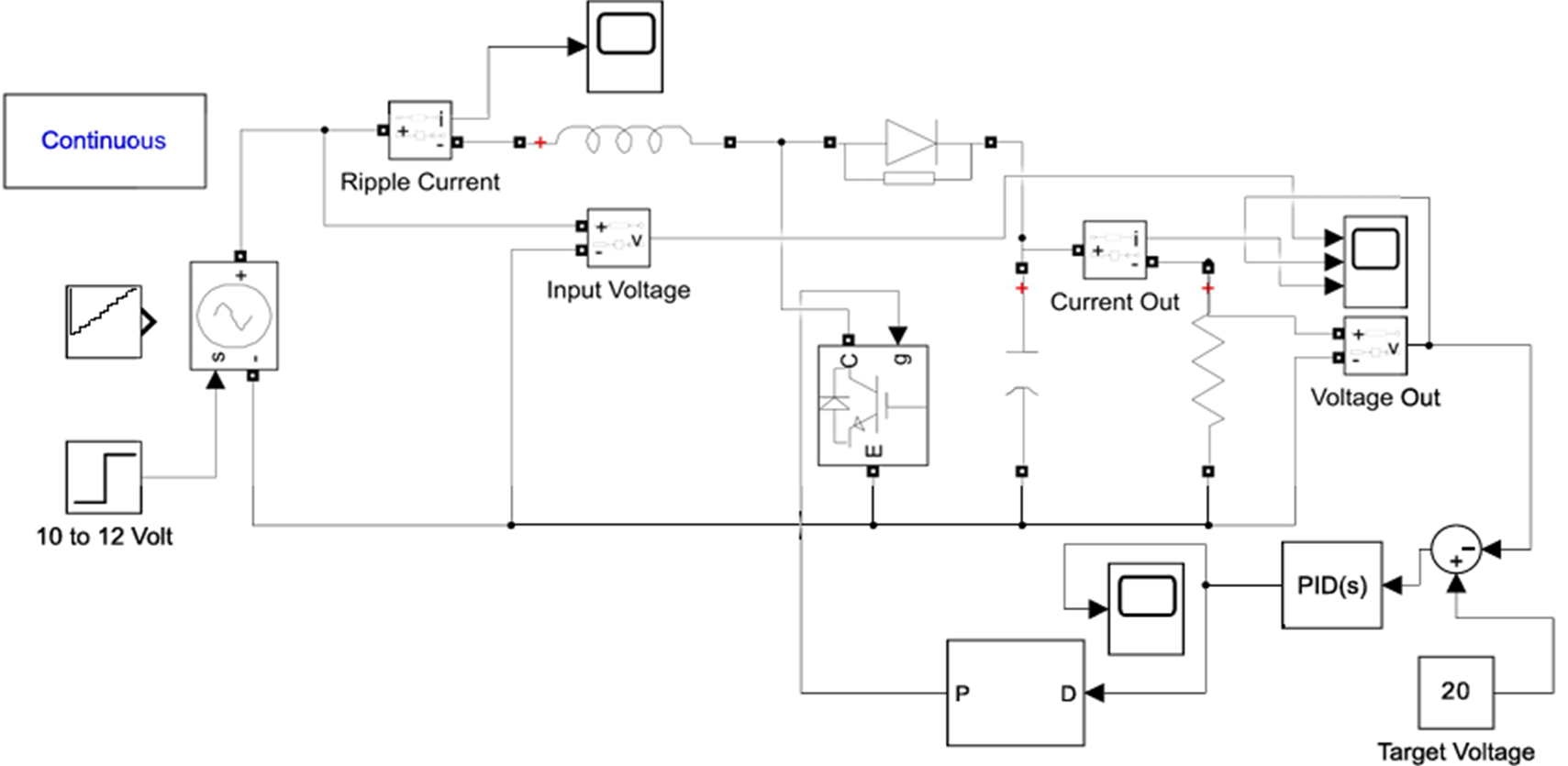
[Figure 4: DC Boost Converter, Closed-Loop Control]
