Spectral Forest
BUILDING THE PROJECT
Final Schematics
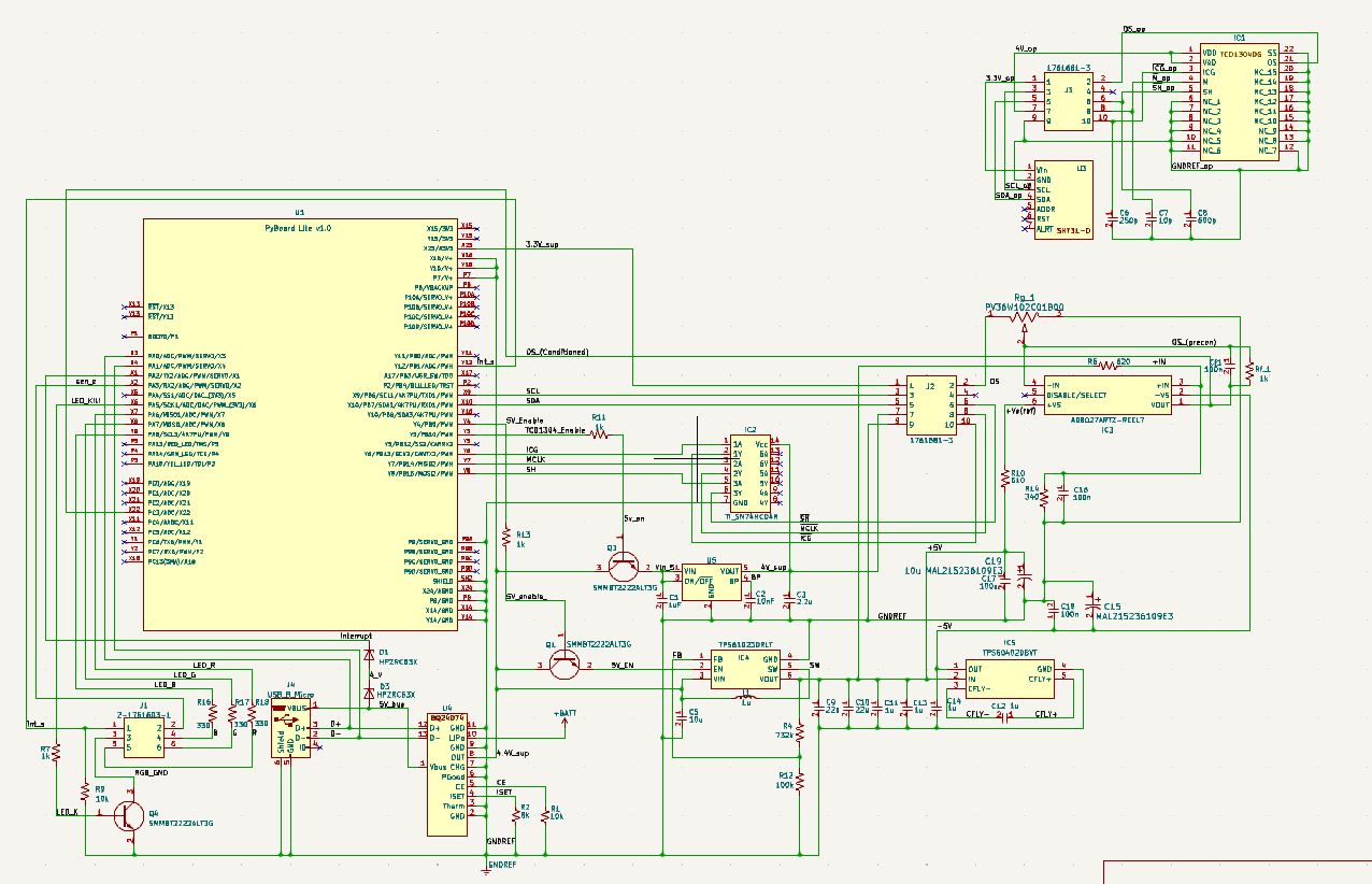
Figure 1:Electrical Schematics Showing Submodules.
3-D Diagrams
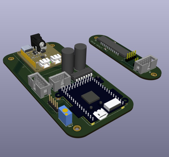
Figure 2:Spectrometer Electronics: Linear Array, Environmental Sensors, & Control/Power PCBs

Figure 3:Spectrometer Electronics: Linear Array, Environmental Sensors, & Control/Power PCBs
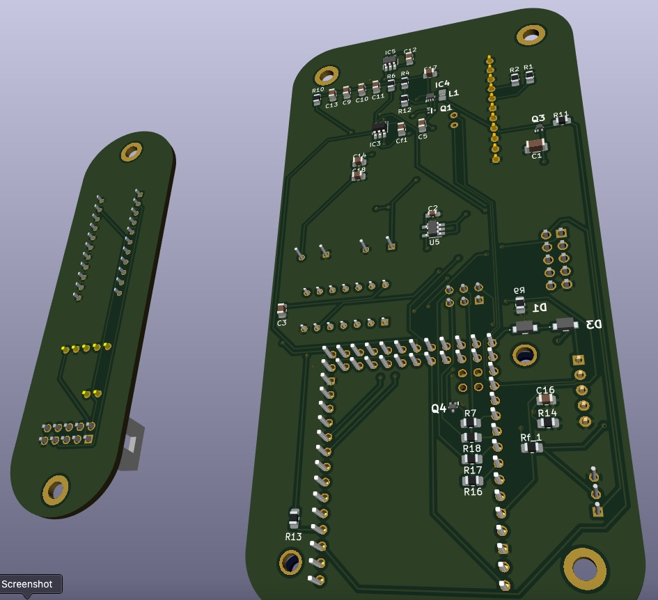
Figure 4:Spectrometer Electronics Bottom View
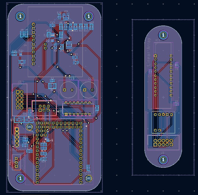
Figure 5:Spectrometer custom PCB: Layer view of front and back
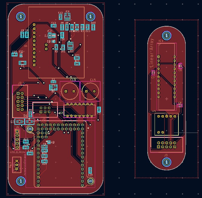
Figure 6:Spectrometer custom PCB: Layer view of front
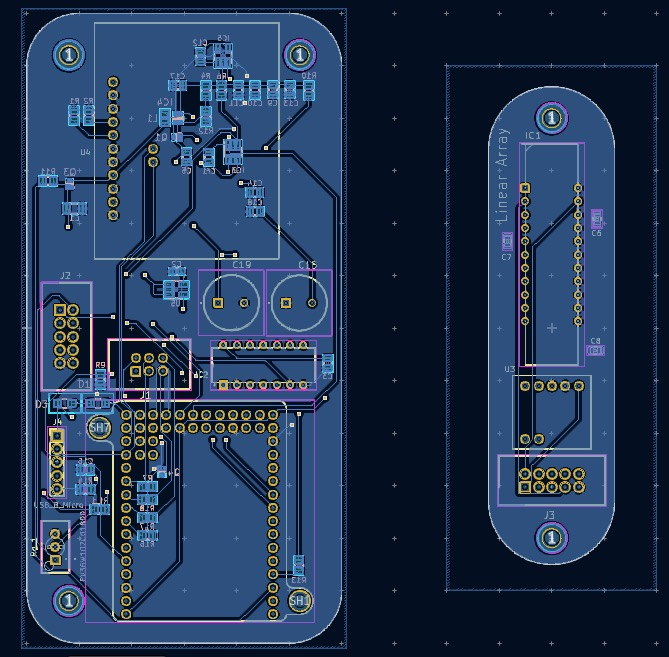
Figure 7:Spectrometer custom PCB: Layer view of back
Prototype
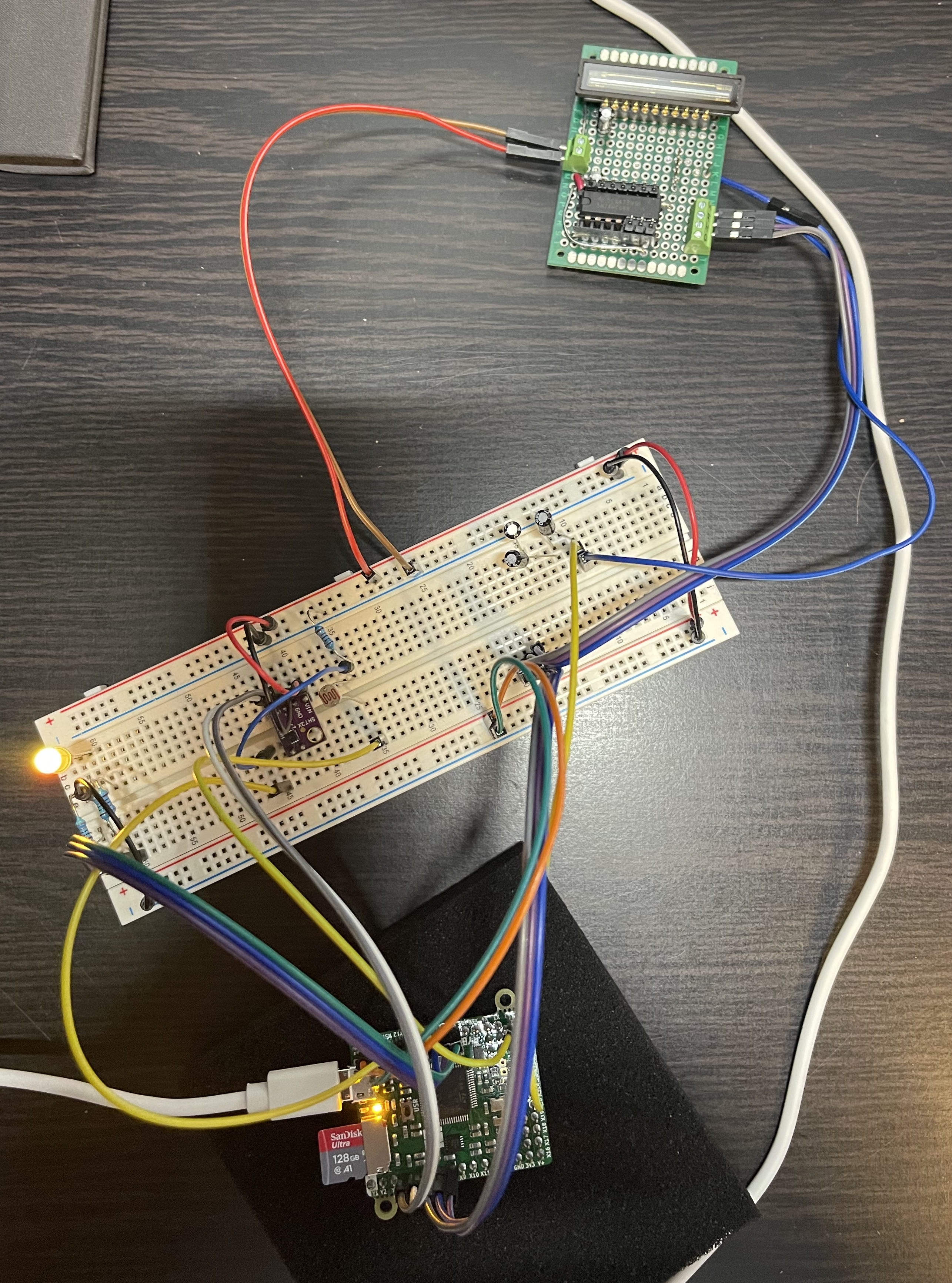
Figure 8: Prototype of linear array, temperature and humidity sensor, and Micropython Pyboard v1.1.
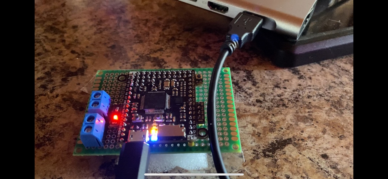
Figure 9:Spectrometer first sleep function test with led indicators
Specifications
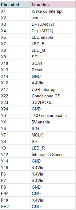
Table 1: Pin Labels represent pins used on the PyBoard as seen in the schematic, with each of their functions listed. Any pins not included have No Connection (N.C.).
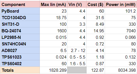
Table 2: Specs of each individual component are listed for absolute maximum ratings. The actual spectrometer will typically not run at these ratings, but it is built for them to ensure it does not overload.
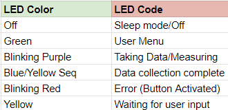
Table 3: LED light patterns are included in hopes of making it more user friendly, giving color codes for certain states of the spectrometer.