Fully Implantable Bioelectric Generator
The charging mechanism for the pacemaker’s battery must ensure sustainability to achieve our goal of prolonging its lifespan and reducing the need for invasive replacement procedures. The product specifications include measurements in amp hour (Ah) and voltage (V) which are compatible with the pacemaker’s battery capacities. St. Jude's Assurity Dual-Chamber pacemaker battery's elective replacement indication (ERI) is at 2.67V, therefore the trickle charging will be initiated around 2.8V and at a rate of 0.19 - 0.57 Ah. Battery management module will be implemented to prevent overcharging and ensure charging efficiency.
The charging system has to be in the body with an integrated energy harvesting system and dimensions similar to or smaller than the pacemaker. The allowable size is 4.6cm x 5.0cm x 0.8cm (H x W x D). Piezoelectric material serves as the energy source. With the placement of the generator near the heart, we can maximize the efficiency of the energy conversion from mechanical deformation to electrical energy.
Piezo material decomposition over time can be resolved through the use of biocompatible materials. Solutions include coating the surface of the generator or encapsulating the generator with bioinert materials, like PTFE, PEEK, or Gore's ePTFE, to prevent the implant from causing scar tissue or immobility
In 2021, U.S. healthcare spending reached $4.3 trillion, which averages to $12,900 per person. With the healthcare cost being at an all time high, it is important we consider the components used. There is a trade-off between the cost efficiency and the rest of the objectives. If we only focus on the other objectives, they can easily escalate the overall project cost

Based on our two constraints given to us by our client, Gore, which is that the generator has to be fully implantable in the human body, and that we can’t use induction to charge the pacemaker battery, we came up with a couple of solutions. The two main possibilities: creating a thermoelectric generator or using piezoelectric materials to charge the battery. We ended up choosing the piezo material generator because we only need a stress, force, or deformation of the material to create electrical energy. This is done through the piezo effect which is just the shift of positive and negative charge centers, creating the electrical field.

The force or stress we will be using to deform the material will be the human heartbeat because it just seems intuitive to use the human body’s natural mechanisms. We also thought about how biocompatible the piezo materials were in the human body, which we will explain more about in a later slide. The reason we went with the piezo instead of the thermoelectric generator was because we needed at least a 2 degree Celsius temperature differential to create the electrical charge. Since the human body has a stable and constant internal temperature, we would need to create an artificial heat source to get that differential. Introducing an artificial heat source raises concerns about safety, as it could potentially lead to tissue damage, or just discomfort overall.
Piezoelectric materials lead to decomposition later in life. Some potential solutions would be coating or modifying the surface of the generator where the body tissue and proteins ignore the implant preventing scar tissue or immobility. Because of this we need a Bio-inert material such as PTFE, PEEK or Gore’s ePTFE. Dr. Becker recommended finding materials used to make the implantable catheters, searching FDA approved material lists, and contacting companies for material samples so that we can test their flexibility to assure that they will work for piezoelectricity
Piezoelectric materials lead to decomposition later in life. Some potential solutions would be coating or modifying the surface of the generator where the body tissue and proteins ignore the implant preventing scar tissue or immobility. Because of this we need a Bio-inert material such as PTFE, PEEK or Gore’s ePTFE. Dr. Becker recommended finding materials used to make the implantable catheters, searching FDA approved material lists, and contacting companies for material samples so that we can test their flexibility to assure that they will work for piezoelectricity
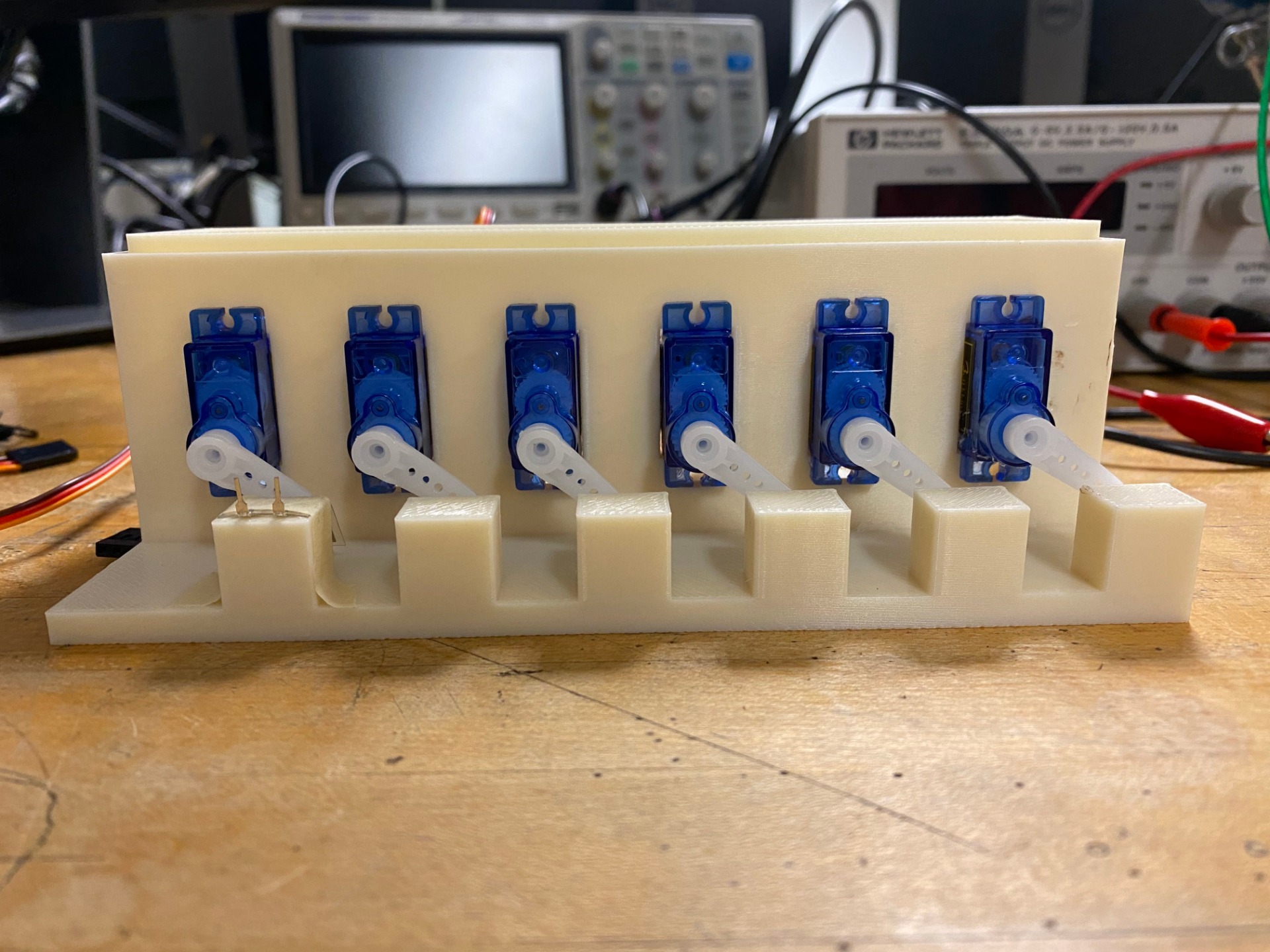
To start our testing procedure methods, we first wanted to incorporate the servo motors to try and replicate the heartbeat to actually deform the material. We set the servo to “Pulse” at 70 beats per minute which is around 1.16 Hz. For our initial prototype, we mounted the servos to legos so they can stay in place. We also mounted the piezos close so the servos can deform the material at an angle to get the best deformation. For our final prototype, we 3d printed the testing mount with ABS material.
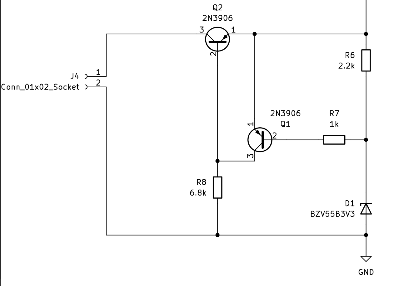
We implemented an overvoltage protection circuit since when recharging batteries, some type of battery management needs to take place. We decided that an overprotective circuit would be sufficient enough since this feature would just shut down the supply, or clamp the output when the voltage exceeds its preset level. To set this preset level, we incorporated a zener diode with a reverse voltage of 3.3V. This allows us to cut the voltage with any level above 3.3V.
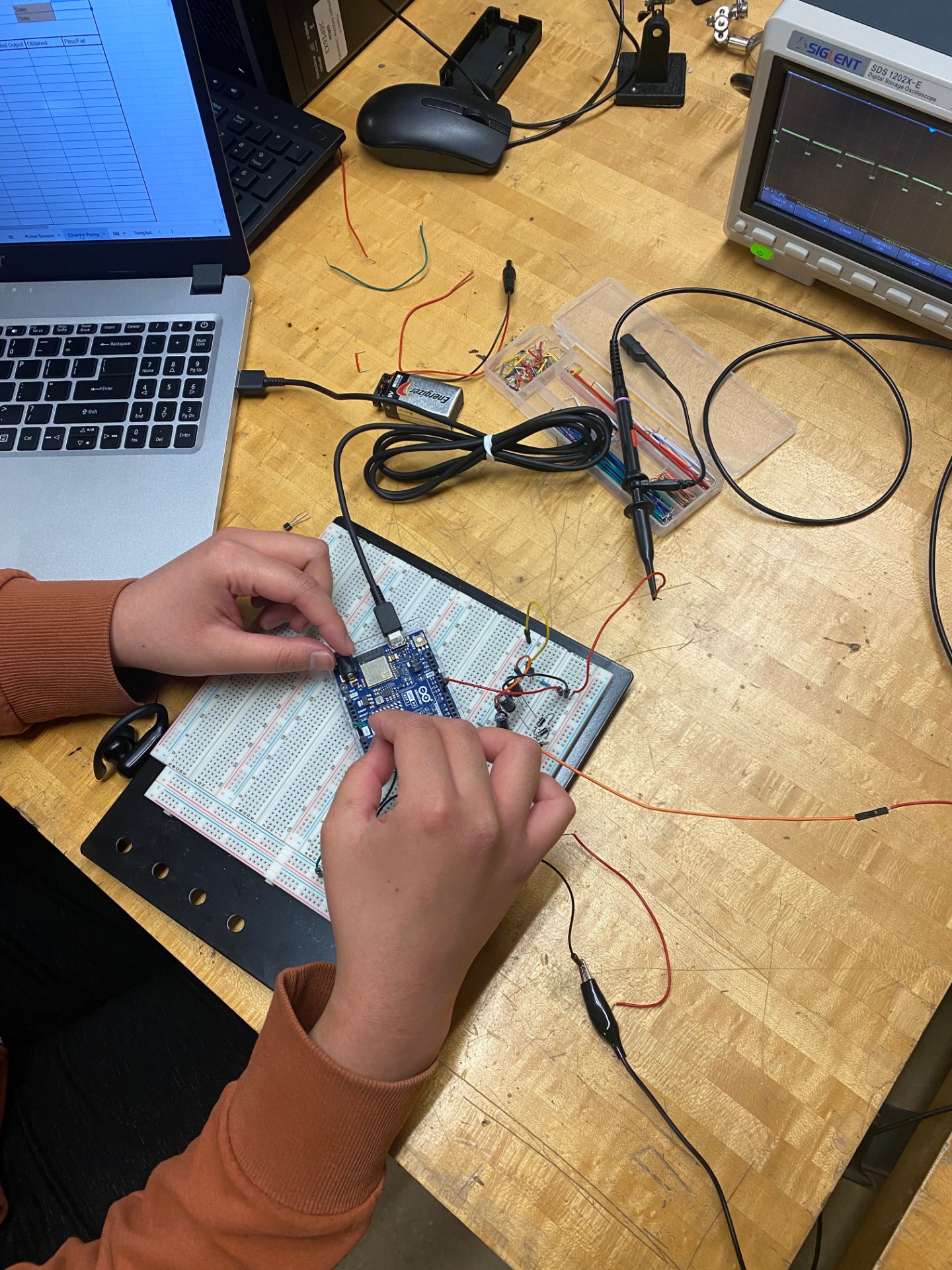
With this project comes numerous problems, and every solution we come up with, more problems seem to arise. The first difficulty we had in the very beginning of our project was the amount of voltage and current needed to power the circuit. Since piezo does not behave like a typical power source, we have attempted a couple of solutions. Despite double stacking the piezo’s (per servo) and increasing the amount of servos, the level of voltage was disproportionate. Adding the amount of piezos in series or parallel was just not a linear increase. It was more of a logarithmic increase where it would ramp up quickly initially, but then steady out the more piezo we added.
We thought about amplifying the signal with an op-amp or boosting the voltage with a charge pump. However, we had to abandon these ideas since the components needed a supply voltage of 3V or higher from the piezo. At that point, we thought we might as well just go straight to the buck boost if we were already getting that supply voltage from the piezo. Another problem found with an original idea was the pulse sensor.
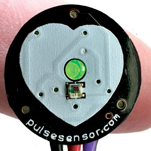
At the very beginning of our project, we were using a pulse sensor so we could accurately move the servo motor at the pace of one of our heart beats. Since it was hooked up to an Arduino, it did display the person’s heartbeat in the serial monitor, however the signals sent to the servos were not precise. Thus, we decided to hard code the servos instead with an avg 70 Beats per minute.
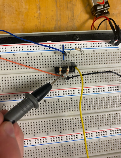
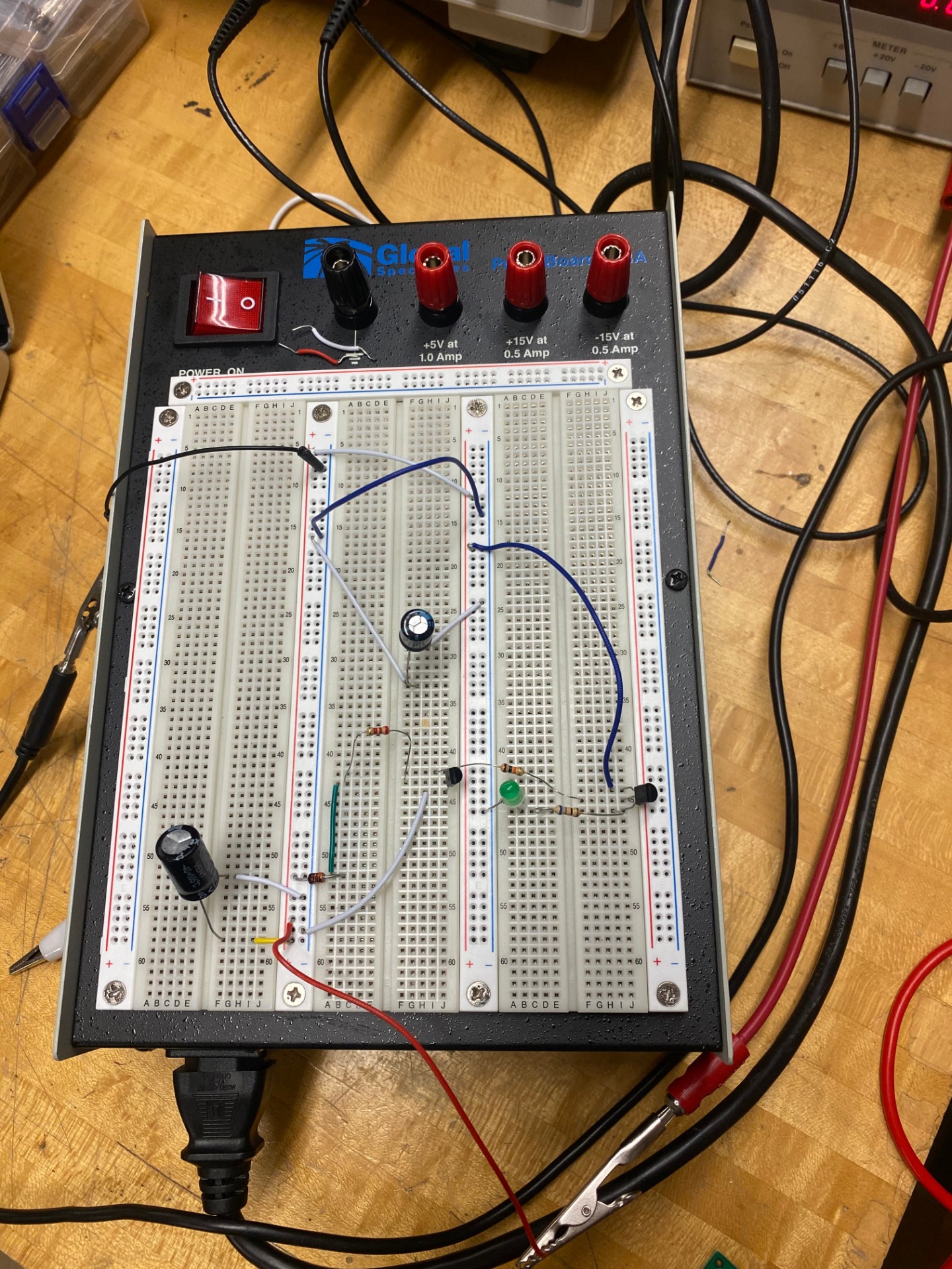
As mentioned before, piezo does not behave at all like a typical power source. When connecting a load with 18 piezos (which we tested in various combinations of parallel and series), even a load as small as a 100 Ohm resistor, caused the voltage to drop to a meager 0.20mV after the rectifier. When connecting it to the buck-boost, there was no voltage.
This led us to consider the capacitor as a battery source instead. We incorporated a mechanical switch to allow the capacitor to charge up and discharge at the needed voltage. It did allow the voltage to climb up. Since the mechanical switch worked, we tried to design a network of BJT transistors with a zener diode. A zener diode is a nifty device that can act in both reverse and forward bias. Meaning that in forward bias it is a normal 0.7V diode, but in reverse bias it can allow current to pass through once the allocated voltage is reached.
We thought this would work as it could activate the switch once 3.3V was reached by the capacitor. But in reality it did not work that way. No matter what we tried, the voltage would still get through the PNPs. We changed out the components but to no avail. Additionally, when we went back to the mechanical switch, the voltage plateaued at 7V in the capacitor. We enabled the switch when the voltage was at or well above the minimum input voltage to the buck boost, but it did not activate the Buck-boost due to the various resistors and capacitors the buck-boost had cutting the voltage and current.
Since our final testing mount and our encapsulation model were created using Solidworks, measurements were needed to ensure correct dimensions of the servo motor holes and the inner dimensions of the encapsulation.
For this we used correctly zeroed calipers to measure the servo motor dimensions at: 12.09 mm W x 32.2 mm H and the dimensions of the printed circuit board in order for the inner dimensions of the encapsulation model to be no less than 64 mm W x 44 mm H x 1.7 mm D.
By using these dimensions and a ± 0.05 solidworks tolerance, we were able to make sure that our 3D printed parts fit our components and needs perfectly!
As part of the design process, we made pairwise comparisons and decision matrices for our major components. The buck-boost converter was weighted with these factors including: input voltage, output voltage, output current, quintessential current, and the PFM Mode. With these parameters in mind, our team decided that ultimately the TPSM83100 won due to the internal inductor since it plays a major role in lowering the input voltage.
Meanwhile, PEEK was finalized as our encapsulation material due to the short amount of time it needed to be acquired and produced for our project and it does not exert cell and tissue toxicity nor adverse immune reaction upon implantation.
Before the idea of op-amps was put to rest, we compared the op amps we found in the cage to select the best one. With these parameters we had in mind which were: The supply voltage, input voltage, output voltage, the respective gain, and the power consumption, The TLC27L9CN won for its higher output voltage and meager power consumption.


created with
Best Free Website Builder .