Pacemaker
A pacemaker is a vital device that allows the heart to maintain a healthy heartbeat rhythm. Like many other electrical devices, the battery needs to be replaced over time due to wear. In order to replace wearing batteries, surgery is required every few years. This procedure is costly and can create risks to the patient. To deter this risk, a bioelectric generator is needed to eliminate the need for battery replacements and surgery.
Objective
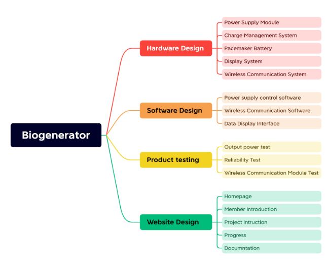
The objective is to design, build, and test an implantable electric generator to recharge a pacemaker. This device will charge the pacemaker battery when the battery level is low. It will also stop charging at the point where it is harmful to the pacemaker battery.
The Requirements (HOQ)
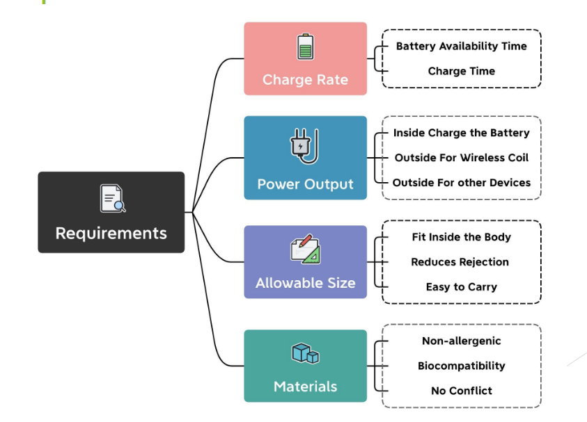
In order to start designing our pacemaker, we need to take into consideration the desired needs of our client. First we need to understand the problem; the important requirements that will allow flexibility for the design process. The requirements have to contain certain properties that will lead to a successful implementation. Each of these requirements need to be abstract; specifies what the system does. They need to be verifiable, and have a way to demonstrate that our design meets the expectations. Lastly, our requirements need to be traceable; each requirement needs to be traced to a specific need of our client. The requirements for our bioelectric generator are:
Charge rate: In order for the pacemaker to function properly, the battery needs to be constantly charged. So we need to measure how long the pacemaker will last before charging it again.
Allowable size: The pacemaker needs to be a certain size in order to fit inside the body without giving disturbance to the user.
Implant Materials: The property materials for the pacemaker takes a major role here, for it contributes to biocompatibility.
Biocompatibility: This is the capability of the pacemaker to coexist with the surrounding tissues without any health complications.
Power output: The performance and efficiency of the pacemaker will be determined by the output power.
Wireless communication with the implant that shows:
Charge level & Charge rate: This is used to monitor the working status of the pacemaker and the charging status in real-time to ensure the safety of the user.
Charging Methods
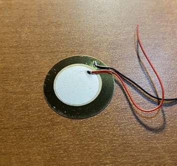
Piezoelectric
Piezoelectricity generates an AC voltage when an object is subjected to vibration.
For this generation, different forms of materials are required, the most common being Lead Zirconate Titanate, but it is harmful to the human body because of lead. Some biocompatible materials such as Zinc oxide (ZnO), Aluminum Nitrate (AIN), and Barium Titanate (BaTiO3).
In order for this to work, it must not require an external voltage source and can be used with small devices. This form works in the vicinity of resonant frequency. This system works well in watches and has been tested with canine hearts.
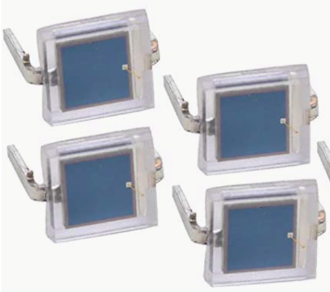
Solar/Photovoltaic
PV technology converts sunlight into electrical energy.
Sunlight consists of photons that collide with a semiconductor solar panel. The panel contains individual cells with positive and negative layers that create electric fields.
So, when the photons hit the solar panel, it creates an electric current harnessed by wires connected on the positive and negative sides of the cell.
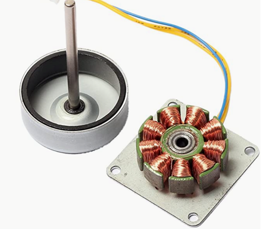
AC Charging
The brushless generator is used to collect energy from human movement and generate alternating currents.
By converting AC to DC through the converter. Then the required output current is obtained through a series of operations such as voltage reduction.
Decision Matrix for Charging Method
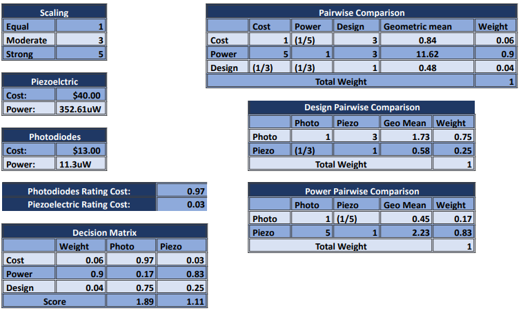
We need to determine the best charging method for our rechargeable pacemaker. For this process, we used the analytical hierarchy process, which can be an effective tool to compare alternative solutions.
The figure below shows the scaling we used, basic information about both charging methods, the photodiodes, and the piezoelectric, as well their pairwise comparison and decision matrix.
We can see those photodiodes have a higher score than piezoelectric, not to mention those photodiodes produce a more constant charge than the other charging methods.
Concept
The Biogenerator will be divided into two parts, the charging part and the power generation part. The implant is the charging part, and the external part is the power generation part.
Charging Part: We plan to use an inductive coil as the charging module and add a power control circuit to ensure a stable output of charging effect. We need to ensure that the implanted part of the body is as small as possible to reduce human rejection.
Power Generation Part: We plan to design a dual power supply design for the external charging device, which on the one hand generates power through Piezoelectricity, so that the patient can generate enough power to charge the pacemaker while performing daily activities. On the other hand, we plan to design an AC Charging module for patients who have mobility problems and cannot generate enough power from the piezoelectric ceramic. This will allow the patient to power the pacemaker from an accessible power source.
Wireless Communication: Thanks to the low power consumption of Bluetooth communication, we plan to use Bluetooth and Raspberry Pi to implement a real-time display of the charging rate and charging level. For ensuring and confirming the proper functioning and safety of the system.
User Interface: We plan to design a user-interactive interface for the display of the charging rate, which can be displayed in real time during the charging process. Heart rate and other indicators can be detected in real time during non-charging processes.
Solar Panel Array
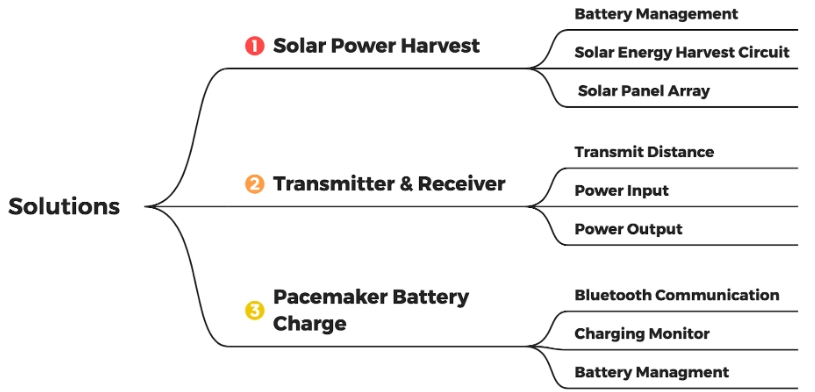
We use two kinds of solar panels.
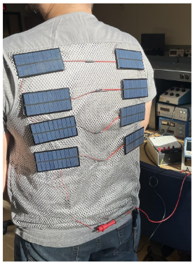
Solar Panel Vest:
For patients who can move normally
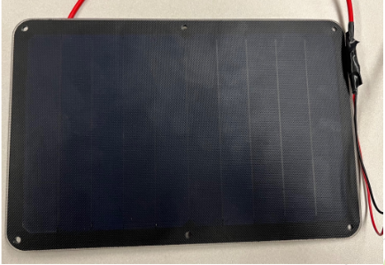
Single Complete Solar Panel:
For patients who need wheelchair
Solar Charge and Battery Management
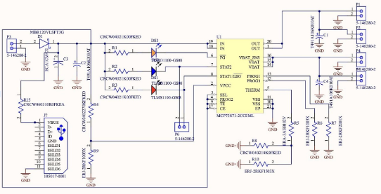
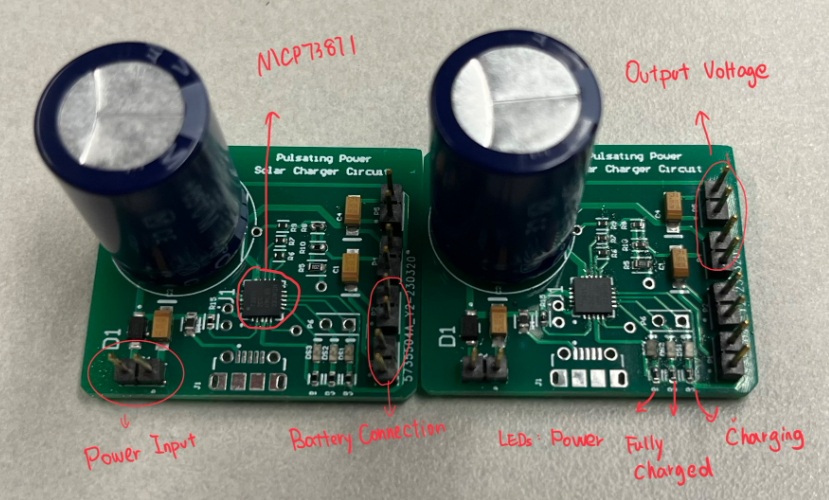
MCP73871: Microchip Technology. Battery Management Circuit.
Input Voltage: 3.7V to 7.0V (Solar Panel Range)
Why do we use the battery outside the body?
The Solar Panel’s power could not drive the wireless coil. We need a battery to have enough power.
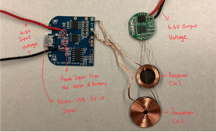
Transmitter And Receiver Circuit
Transmitter Allows Two Power Input Ways:
Solar: A circuit cell directly connected to the solar energy can drive the coil directly if there is enough energy in it
Micro USB: If an emergency requires the use of the coil, the input port of the Micro-USB allows direct powering of the coil via 5V 1A current.
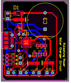
PCB Design
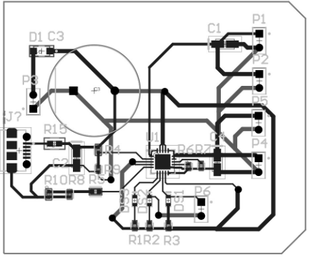
MCP73871 Solar Energy Harvest Circuit PCB Design 2D View
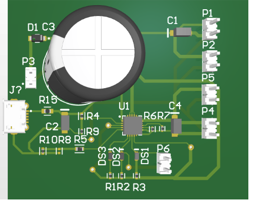
MCP73871 Solar Energy Harvest Circuit PCB Design 3D View
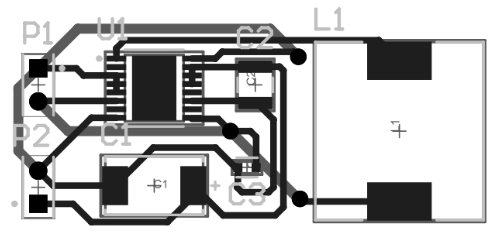
TPS61032 3.7V to 5V Boost Circuit 2D View
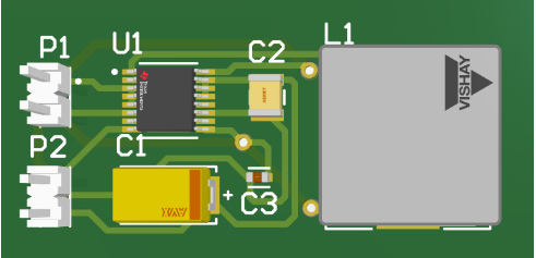
TPS61032 3.7V to 5V Boost Circuit 3D View
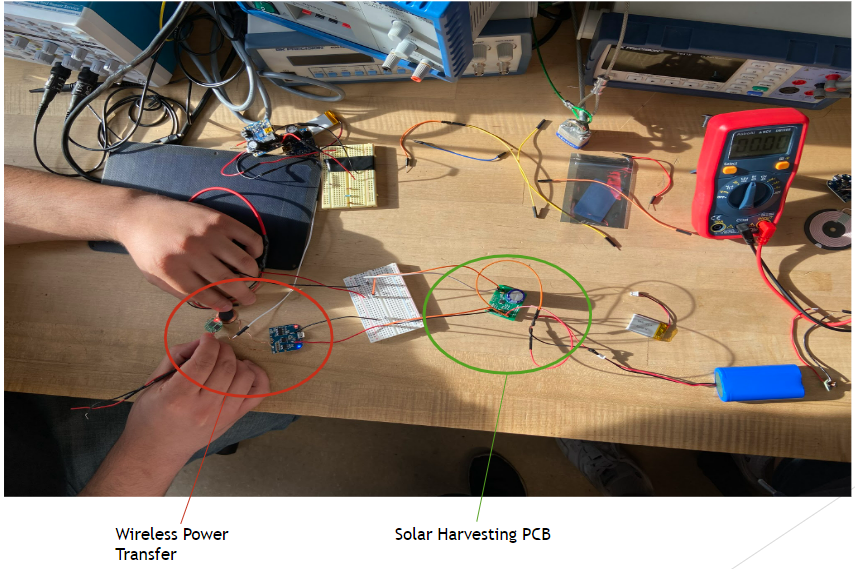
Solar Harvesting Prototype Full System
Challenges and Failures
The hardware design needs to take full account of the various scenarios.
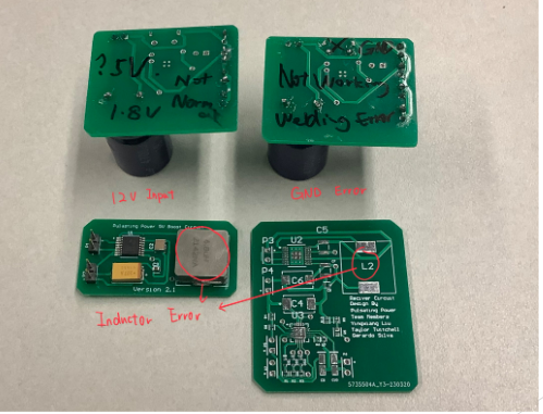
Due to our lack of experience, the original TPS61032-based boost converter design used too large an inductor and did not work properly.
We did not do proper measurements before testing due to our eagerness to do testing.
This resulted in two finished circuit boards burning up. The reasons for the burnout were the high 12V input voltage and the reversed battery and Load connections.
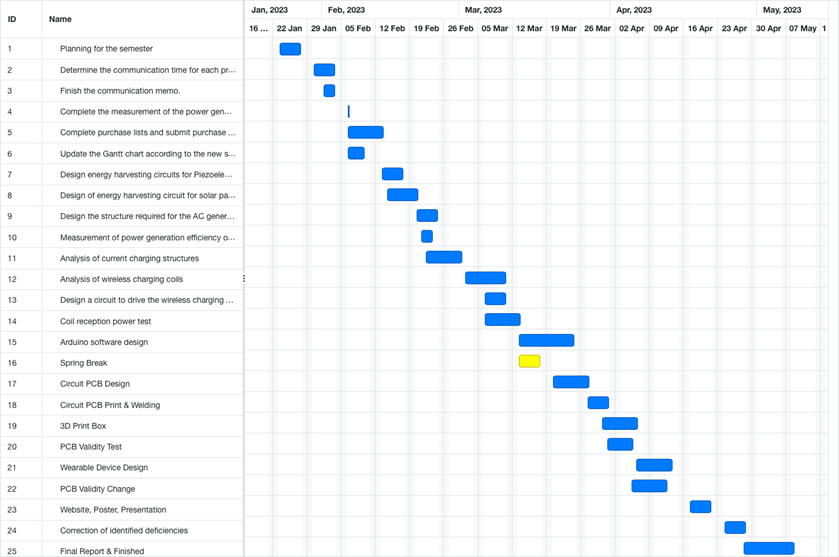
Gannt Chart
Information on Project Sponsor
At W. L. Gore & Associates, their products are designed to be the highest quality in their class and revolutionary in their effect. They resolutely live up to their product promises, and their associates address technical challenges with innovative, reliable solutions.
Gore creates next-generation cable assemblies and components for the electronics industry, sets the standard for outerwear comfort and protection, solves complex industrial problems with innovative materials and technology, and Gore medical products work in harmony with the body's tissues to restore normal body function.
W. L. Gore & Associates was founded on January 1, 1958, in Newark, Delaware, by Wilbert L. (Bill) and Genevieve (Vieve) Gore. Founders Bill and Vieve Gore started W. L. Gore & Associates in the basement of their home in 1958. The company initially served the electronic products market. Gore has achieved long-term success in translating dreams into tangible, valuable realities for customers and communities worldwide.
To learn more about Gore, please click here.
