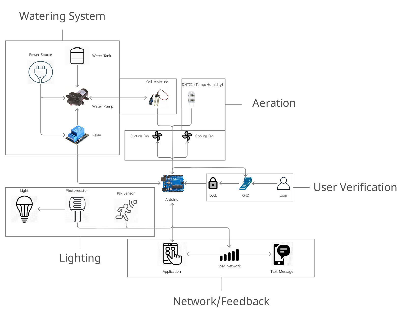
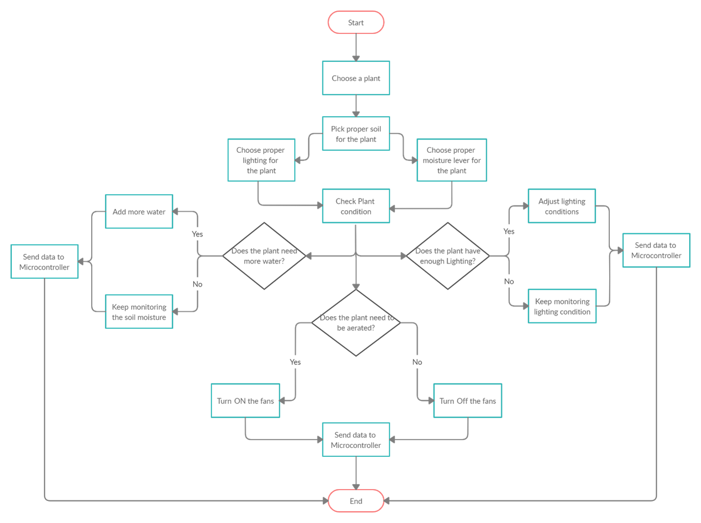
System Architecture


|
1 |
RFID Scanner |
|
1.1 |
System will register & recognize 5 different users |
|
1.2 |
The scanner will send either a granted or denied signal microcontroller |
|
2 |
Physical Security |
|
2.1 |
A lock will automatically open when a verified user tries to access the system |
|
3 |
Camera |
|
3.1 |
The camera will snap picture based on motion |
|
3.2 |
The camera will provide a live feedback to the user (Optional) |
|
4 |
Feedback (Optional) |
|
4.1 |
A text message will be sent to the user via a GSM network for alerts |
|
4.2 |
An LCD Display will indicate the user |
|
4.2.1 |
Green (Granted access) |
|
4.2.2 |
Red (Denied access) |
|
5 |
Water Tank will provide the water to the system, we assume that it will always be full |
|
6 |
Water Pump 1 and 2 will be On until the moisture sensor reading reaches a certain moisture level |
|
6 |
Pump will provide water from a tank into the drip system |
|
7 |
Drip System |
|
7.1 |
Will provide water in a certain pattern depending on the plants need of water, (might not use, since that the soil moisture sensor already controls the flow of water.) |
|
7.2 |
Will have a separate drip system for each chamber for better water control (Optional) |
|
8 |
water |
|
8.1 |
The control system will monitor the moisture and control the pump |
|
9 |
Network/Security |
|
9.1 |
The control system will monitor the motion |
|
9.2 |
The control system will store security information |
|
9.3 |
The control system will monitor network condition |
|
10 |
Lighting |
|
10.1 |
The control system will monitor the lighting conditions within the chamber and control the lights |
|
11 |
Aeration |
|
11.1 |
The control system will monitor humidity, temperature and control the fans |
|
11.2 |
Every hour the suction fan will receive a signal to turn ON for 30 to 60 seconds. (Depends on Temperature / Humidity) |
|
11.3 |
Heating/Cooling fans will remain ON, until a temperature is reached. |
|
11.4 |
Heating/Cooling fans will remain ON, until a temperature is reached. |
|
11.5 |
Suction Fan will turn On until a good air quility is reached |
|
11.5 |
Mode 2: Heating and cooling fan is signaled ON, they will stay ON for 30 mins. |
|
12 |
Temperature |
|
12.1 |
Temperature sensor will send and receive a signal to the microcontroller |
|
13 |
Lighting |
|
13.1 |
Photoresistor will send and receive a signal to the microcontroller |
|
13.1.1 |
Photoresistor will send a signal to turn ON/OFF the lights |
|
14 |
Aeration |
|
14.1 |
Humidity sensor will send and receive a signal to the microcontroller |
|
15 |
Moisture |
|
15.1 |
Moisture sensor will send and receive a signal to the microcontroller |
|
16 |
Security |
|
16.1 |
PIR sensor will send and receive a signal to the microcontroller. |
|
16.2 |
PIR sensor will send a signal (input) to the camera |
|
16.3 |
Camera will snap a picture (output) |
|
17 |
Application |
|
17.1 |
Will provide the user with the proper data |
|
17.1.1 |
Moisture |
|
17.1.2 |
Temperature |
|
17.1.3 |
Air Quality |
|
17.1.4 |
Lighting |
|
17.1.5 |
Security Alert |
|
18 |
Text message |
|
18.1 |
Security alert will be sent based on the RFID scanner and PIR sensor |

created with
Web Design Software .