Problem Overview
Problem statement as given by our sponsor:
Problem 1
- -Soldiers and Marines (US and Allied) going MIA in Iraq and Afghanistan
- -Locating and rescuing is extremely difficult
Problem 2
- -"I want to engage targets in 'that' area... Where are my individual soldiers?"
- -Friendly Fire caused by Air Force bombs, Marine or Army Artillery is
- unacceptable in any circumstance.
- -Eliminate(minimize) fratricide
Problem 3
- -Conducting training and after-action-reviews(AARs)
- -"Are the trainees in their expected locations during the exercise?"
Requirements and Specifications
No explicit requirements were given by our sponsor due to the nature of the project.
All requirements were self-imposed and reflect our goals rather than hard requirements.
Mechanical
- These requirements cover the "physical" aspects of the device, such as the
- device’s size and weight. Ideally the device should be as small and as
- light as possible so that it can be easily carried by a soldier.
- -Size: Less than 3”x2”x2” (plus ~3” antenna)
- -Weight: Less than 8 ounces (~230 grams)
Electrical
- These requirements cover the electronics of the device, such as power
- consumption, what interfaces the device has, and how long the device should last.
- -Power: At least 5.5 Volts, 1 Amp, 2000 mAh Supply
- -Battery: At least 72 hours, Rechargable
- -Interfaces: RS-232 Serial Port, RP-SMA Antenna Connection
- -Device Life: More than 5 Years Under Military Conditions
Environmental
- These requirements cover the environmental aspects in which the device should
- perform, such as temperature and humidity. The device should be able to perform
- reliably in combat conditions. In reality, the device will only be evaluated in fairly
- controlled environmental conditions.
- -Temperature: -40º to 85º C
- -Humidity: 95% max (non-condensing)
- -Shock: Able to withstand a drop from 10 feet
- -Vibration: Able to withstand vibrations present in moving vehicles
Software
- These requirements cover the software aspect of our design. The commander's
- unit will connect to a laptop or PDA running the mapping software. The software
- to be used should have at least the following capabilities.
- -Internet: Should be able to operate without internet connection
- -Mapping: Include major landmarks, roads, bodies of water, etc.
- -Interface: Easy to navigate, change settings, view location of devices
- -Stats Displayed: Directional vector, velocity, location, personal information
- -Other Features: Geo-Fence, Alert indicator when soldier is in distress
General
- These requirements cover the general operability of the device. Our goal is to be
- able to locate the device from several miles away and with reasonable accuracy,
- such as being able to tell which building the device is presently in, or last entered.
- Additionally, the device will have an "SOS" feature which indicates to the
- commander's device that the soldier is in trouble. For instance, if the soldier goes
- outside a specified area, the SOS will automatically be sent. This distress signal
- should be implemented in such a way that a captured device cannot be
- maliciously set off to set up an ambush.
- -Outdoor Range: ~15 miles (with line-of-site)
- -Indoor Range: ~2000 feet
- -Outdoor Accuracy: Less than 10 meters
- -Indoor Accuracy: Less than 30 meters
- -"SOS" Mode: Can be manually or automatically triggered (Geo-Fence)
System Diagram

We designed the system so that both the commander's device and the soldier's device
were identical, with a slide switch determining the "mode". Both devices receive
their geographic location from a GPS module. In "Soldier Mode" the location is sent
over radio to the commander's device. In "Commander Mode" the device receives the data
sent from the soldier's device and displays this data on the computer screen via third-
party GPS tracking software.
Budget

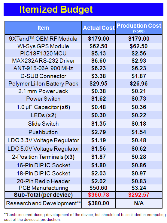
The itemized budget allows an easy comparison between what our device cost to build, and what the cost would be if put into mass production. Obviously the cost decreases significantly when components are bought in large quantity. Research and Development costs include radio development boards, cables, battery chargers, and other accessories not directly related to the functioning system.
Results

After completing the initial design for the system, we created a layout for a Printed
Circuit Board and had this board manufactured to our specifications by ExpressPCB.
This allowed us to mount all the components to the board for a more professional
appearance and made the device easier to test and ultimately, to demonstrate.

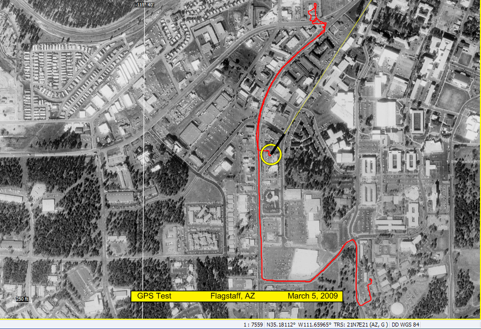
The map above is the result of a test done in Flagstaff Arizona using the GPS module and the ExpertGPS software. The red line is the trace of our path starting from NAU's central campus and driving on Milton road until it meets Route 66. The yellow circle shows our present location and the black and yellow line shows the direction we were heading at that moment.
These results indicate that our accuracy goals were met and exceeded by far. Our initial goal of outdoor accuracy was less than 10 meters, but in reality the accuracy is closer to 2 meters.
References/Tools used
ExpertGPS
ExpressPCB
PIC BASIC Pro
Angelfire GPS Payload
|


