THE PROJECT
The Problem
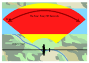
One component of this system is a gimbal mounted radar antenna.
A device known as the Modular Electronics Unit (MEU) controls this antenna through communication with a servo controller connected to the gimbal.
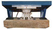
Furthermore, any damage done to the gimbal or antenna that is a result of faulty input received from the MEU is costly to repair, making debugging the MEU difficult.
The Solution
The team created a simulation of the gimbal-antenna assembly.
This simulation will stand in place of the actual assembly for the purposes of testing and developing the MEU.
 By running the simulation on an ordinary personal computer, and connecting a serial cable between this computer and the MEU, the MEU will be able to send commands and receive responses just as if it were communicating with an actual assembly servo controller directly.
A Graphical User Interface (GUI) allows the operator of the system to visually observe the motions of the simulation, just as they would observe the motions of the actual device.
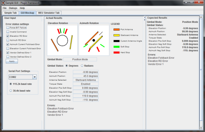
The above image is a snap shot of the team's simulator in the Plug-in Framework. A more in depth discussion about the features behind this User Interface will be explain in the "Architecture" section below.
This simulation will stand in place of the actual assembly for the purposes of testing and developing the MEU.

A Graphical User Interface (GUI) allows the operator of the system to visually observe the motions of the simulation, just as they would observe the motions of the actual device.

The above image is a snap shot of the team's simulator in the Plug-in Framework. A more in depth discussion about the features behind this User Interface will be explain in the "Architecture" section below.
Requirements
Functional Requirements:
- Commands and responses between the simulation and the MEU must be sent over a serial connection.
- All data communication must be transferred in a specific byte packet format, defined by Lockheed Martin.
- The team's developed user interface must utilize the Lockheed Martin Plug-in Framework (LMPF)
- The LMPF is a library written in Java, which provides a central and consistent user interface for the testing of various Lockheed Martin products.
Architecture
In this section the team will discuss the underlying architecture that the simulator is based on. The first image is an architecture overview of the simulator application. Each image after that is a zoomed-in view of a specific component of the application.
 OVERVIEW
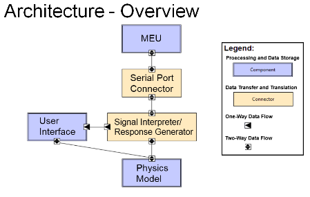
The image to the right is a broad overview of the application the team created. However not all components shown were added to the final deliverable to our client.
The actual simulator and product we provided to our client was comprised of the following three components: (1) Signal Interpreter/Response Generator, (2) Physics Model and (3) the User Interface.
The "Serial Port Connector" was a part of our requirements for serial communication with the rest of the system that Lockheed Martin maintains.
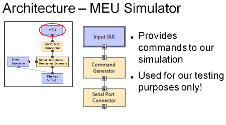
The "MEU" component in the team's architecture is a pseudo copy of the original Modular Electronics Unit (MEU) that Lockheed Martin owns. The team's copy is for the team's testing purposes only and it only functions to send commands through serial communications.
 MEU ARCHITECTURE
The image to the left is sub-architecture view of the MEU that the team created. This MEU is a striped down version of the original and is used by the team for testing.
The team created a simple user interface that users could use to issue a command; such as, setting the "Position Mode" at 15 degrees elevation and 150 degrees azimuth.
When a command is set by the user from the interface the command is formatted into the specified byte string through the "Command Generator". Then the MEU application sends the formatted command through the serial port.
 PHYSICS MODEL
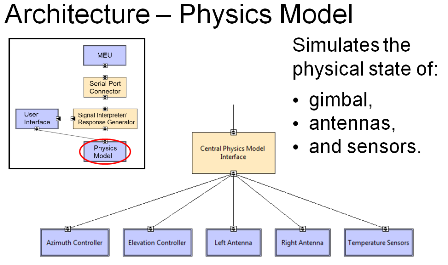
The image to the right is shows the sub-architecture view of the Physics Model. This component of the application is given an interpreted command and performs action based on the command.
When a formatted command is sent to the "Central Physics Model Interface" the command is processed and either pulls or pushes information to the sub classes that represent the gimbal antenna.
 GRAPHICAL USER INTERFACE
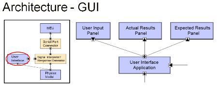
The image to the right represented the sub-architecture for the Graphical User Interface (GUI). This component handles the data display to the user. The main component to the GUI is the "User Interface Application", but this component is actually comprised of three other components: "User Input Panel", "Actual Results Panel", "Expected Results Panel".
The User Input Panel contains user interface components for the user to input events; such as, using checkboxes to set environmental error flags that change how the system works. This component is the far left panel in the application.
The Actual Results Panel contains all the interface components for the user to see what's going on in the simulated antenna. This panel contains two graphical images that rotate in the elevation and azimuth rotation. So users can see a simulated, real-time, model of the antenna moving when a command is sent to antenna. Below those graphics is a listing of properties that tells the status of the antenna. This includes elevation, azimuth location, antenna selection, positive & negative soft stops, and which error flags have been set.
The last panel, Expected Results Panel, hold status information that was last sent by the MEU. The reasoning to have this panel is so that the user could see a comparison between what the MEU thinks should be happening to what is actually happening.

The image to the right is a broad overview of the application the team created. However not all components shown were added to the final deliverable to our client.
The actual simulator and product we provided to our client was comprised of the following three components: (1) Signal Interpreter/Response Generator, (2) Physics Model and (3) the User Interface.
The "Serial Port Connector" was a part of our requirements for serial communication with the rest of the system that Lockheed Martin maintains.
The "MEU" component in the team's architecture is a pseudo copy of the original Modular Electronics Unit (MEU) that Lockheed Martin owns. The team's copy is for the team's testing purposes only and it only functions to send commands through serial communications.

The image to the left is sub-architecture view of the MEU that the team created. This MEU is a striped down version of the original and is used by the team for testing.
The team created a simple user interface that users could use to issue a command; such as, setting the "Position Mode" at 15 degrees elevation and 150 degrees azimuth.
When a command is set by the user from the interface the command is formatted into the specified byte string through the "Command Generator". Then the MEU application sends the formatted command through the serial port.

The image to the right is shows the sub-architecture view of the Physics Model. This component of the application is given an interpreted command and performs action based on the command.
When a formatted command is sent to the "Central Physics Model Interface" the command is processed and either pulls or pushes information to the sub classes that represent the gimbal antenna.

The image to the right represented the sub-architecture for the Graphical User Interface (GUI). This component handles the data display to the user. The main component to the GUI is the "User Interface Application", but this component is actually comprised of three other components: "User Input Panel", "Actual Results Panel", "Expected Results Panel".
The User Input Panel contains user interface components for the user to input events; such as, using checkboxes to set environmental error flags that change how the system works. This component is the far left panel in the application.
The Actual Results Panel contains all the interface components for the user to see what's going on in the simulated antenna. This panel contains two graphical images that rotate in the elevation and azimuth rotation. So users can see a simulated, real-time, model of the antenna moving when a command is sent to antenna. Below those graphics is a listing of properties that tells the status of the antenna. This includes elevation, azimuth location, antenna selection, positive & negative soft stops, and which error flags have been set.
The last panel, Expected Results Panel, hold status information that was last sent by the MEU. The reasoning to have this panel is so that the user could see a comparison between what the MEU thinks should be happening to what is actually happening.
Project Timeline
This section will cover our project timeline. The design methodology the team adopted was a "Modified Waterfall" method. In a "Pure Waterfall" method, stages of the timeline are broken into a linear process of: Requirements, Design, Implementation, Testing, and Acceptance. In the team's method, majority of those stages remained linear; however, some components of the application needed to be iteratively recursed. For example, the user interface had to go through a couple of reviews from our client before the final deliverable. This was to make sure that our client was satisfied.
As the team was entering the Implementation stage of the project timeline, the team proposed a three phase timeline to keep the team on track on the project. Below is an overview of each of the phases.
PHASE 1
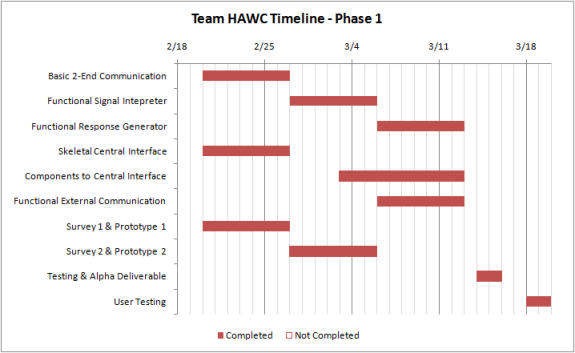 After team had all the requirements and documentation out of the way, the team broke up the simulation application into sub-components and was each component was given to a member to work on individually. So phase 1 was focused on getting all the components implemented and working correctly.
PHASE 2
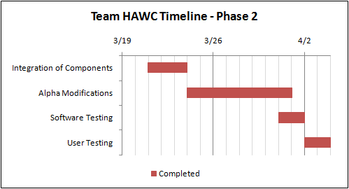 Once all the sub-components were completed, phase 2 was solely dedicated to integrating all components to create our initial alpha prototype.
PHASE 3
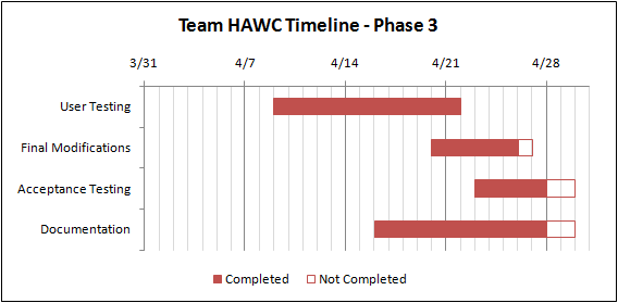 The last phase was dedicated to finalizing and refining our application. At the end of this phase we provided our client with a final beta deliverable.
As the team was entering the Implementation stage of the project timeline, the team proposed a three phase timeline to keep the team on track on the project. Below is an overview of each of the phases.
PHASE 1

PHASE 2

PHASE 3

Final Deliverables
This section shows our final results of our project. The team completed the project and sent the final deliverable to our client. The project code is not open source and cannot be viewed here. All code was passed on to our mentor and client. However resources of the project are provided below:
MANUAL
The final manual we presented to our mentor and client can be found HERE
JAVADOC
Our client required we create a javadoc for our project. You can find the javadoc HERE
FINAL POSTER
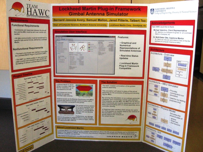
The following picture is the poster we presented during our UGRAD Presentation Day.
MANUAL
The final manual we presented to our mentor and client can be found HERE
JAVADOC
Our client required we create a javadoc for our project. You can find the javadoc HERE
FINAL POSTER
The following picture is the poster we presented during our UGRAD Presentation Day.


