Project Description
The purpose of the Malabar Winters Campground Road Design project is to design a proposed access roadway for a campground north of Williams, AZ. The site is located west of Flagstaff, AZ, and will have up to 12 campsites, three cabins, personal facilities, and a maintenance building. Approximately 1500 ft of gravel roadway will be designed to access the facility with spurs and parking to each site or cabin. The project aims to develop a green property with all necessary aspects including proper drainage and road design, structurally suitable soil, ample parking, and an ingress/egress evaluation. The proposed design must meet the Coconino County and client requirements and have the potential to be used for the client’s long-term planning.
The parcel allocated to the site of this project is located at 6195 N Joshua Tree Road, under Parcel Number 202-02-088 in Coconino County. The site is identified as a G Zone for general agricultural or rural residential land use. The proposed site location is a rural forested area, with existing access provided by the minor rural Joshua Tree Road running parallel to AZ-64. All nearby parcels are owned individually by private owners. To the west of AZ-64 is a partially developed suburb defined as an AR zone, for agricultural residential land uses. Beyond this development is the Grand Canyon Railway. Joshua Tree Road serves as an unpaved access road for the site parcel and the two adjacent to it, for which care must be taken regarding maintenance, ingress, and egress.
Project Location
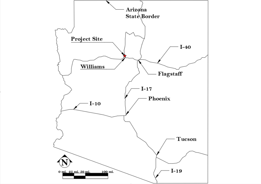
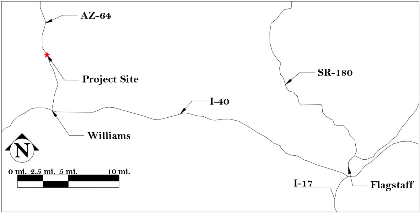
The project site is located in Arizona, approximately 5.8 miles north of Williams along AZ-64. The site can be located using the maps shown below.


Project Constraints
Several potential challenges may arise during the project. Inclement weather such as snowfall will prevent adequate data collection for surveying and make soil sample collection difficult. To remedy this issue, data will be collected before the first snowfall of the year. The existing soil in the area may or may not be adequate for use in this project. If the soil tests yield unfavorable results, additional fill material will have to be brought in and as a result, increase the cost of this project. If the soil is entirely unsuitable, stabilization or full subgrade replacement may be needed instead. The road will have to be designed around mature trees, with a diameter ranging from 15-35 inches and a height ranging from 55-90 feet [4], as they are protected and cannot be removed. As such, this will inhibit an ideal road design and may force the road to take a different path than initially planned. The trees limit the methods of surveying available as drone/GPS are rendered ineffective by the tree cover, indicating that total station collection is necessary. The preliminary site layout provided by the client may be inadequate and be subject to redesign, specifically the amount of parking for each cabin and other buildings.
Scope of Work
This section details the project’s scope of work. Each task outlines a specific element that is needed for the project’s completion. Any work that the team will not complete is shown in Exclusions.
Task 1: Obtain Existing Data
This task includes obtaining the site's existing conditions to gain an understanding of the current site conditions. This includes gathering soil and topo data for the site from current records as well as property boundaries.
Task 1.1: Topo Data
Use Coconino County GIS and Coconino County Parcel Viewer to view the site's available topo data and determine property boundaries and any potential monuments. Draw property boundaries in CAD before going to the site to help orient the topo map correctly.
Task 1.2: Soil Data
Obtain the site’s soil data from the USDA Web Soil Survey (WSS) [5]. This includes any data necessary to determine bearing capacity, hydraulic conductivity, swelling capacity, and other geotechnical design criteria.
Task 2: Site Investigation
This task includes a detailed site investigation including planning, surveying, and determining all essential information from data obtained during this process.
Task 2.1: Site Visit Planning
Complete the NAU Field Safety Checklist Form, detail all activities that need to be completed during the visit, and create an equipment/tools checklist. Input all needed site locations such as survey monuments and property corners into a GPS mapping software for field access, plan site parking and communication with neighbors, and then gather equipment needed prior to the survey.
Task 2.2: Land Survey
Conduct a land survey of the site using a total station. Survey the nearest National Geographic Survey (NGS) monument to tie data into existing information. Ensure that changes in slope, mature trees, and property boundaries are measured. Take pictures of notable site features, such as drainage paths, property boundaries, changes in slope, boulders, and the proposed roadway alignment.
Task 2.3: Topographic Map
Use existing topo data from Coconino County and data gathered during the land survey to create a topographic map of the site and surrounding area using CAD. Identify key features such as utility locations, major vegetation, property boundaries, and flow lines.
Task 2.4: Ingress and Egress Assessment
Determine the safety and ease of entering and exiting the site under normal use cases such as day-to-day operations and during emergency use cases such as wildfire evacuations. Assessment includes determining if emergency, maintenance, and recreational vehicles are able to safely and effectively enter and exit the site.
Task 3: Geotechnical Analysis
This task includes using the soil data gathered from the WSS to determine the bearing capacity and evaluate if the soil is suitable for a road design project based on AASHTO requirements for the roadway subgrade.
Task 3.1: Determine Bearing Capacity
Conduct soil classification and geotechnical analysis to determine the bearing capacity of the soil based on characteristics from the WSS. Soil analysis that can be used to determine the bearing capacity of the soil includes Terzaghi’s Equation.
Task 3.2: Determine Suitability
Use the results from the geotechnical analysis to determine if the soil at the site is suitable for a roadway design. If it is not, then other soil will be used for the backfill or the soil will be stabilized.
Task 4: Hydrologic Analysis
This task consists of all calculations required to determine the hydrologic characteristics of the parcel and nearby area. The result of this analysis is the determination of the rainfall depth and storm flow from the design storm specified by CC [6]. This task is required in order to determine the drainage needs of the site and proposed roadway.
Task 4.1: Watershed Delineation
Delineate the site’s watershed using topographic data in ArcGIS, or by hand using topographic data gathered in Task 1.1. Use StreamStats as a supplemental source for validation purposes [6].
Task 4.2: Determine Rainfall Intensity
Determine the rainfall intensity using the IDF curves published in NOAA Atlas 14. Use Sections 3.2 and 4.3.3.2 of the Coconino County Drainage Design Criteria Manual (CCDDCM) to find the storm duration and frequency required to determine the intensity.
Task 4.3: Determine Time of Concentration
Calculate the Time of Concentration as established in Section 2.2.4 of the ADOT Hydrology Manual. Determine the required slope calculation method upon completion of the land survey, as knowledge of existing grade breaks is required. Determine the Time of Concentration for both sheet flow and open channel flow.
Task 4.4: Determine Peak Flow
If the watershed does not exceed 160 acres in size [7], use the rational method to determine peak flows per Chapter 2 of the ADOT Hydrology Manual. Determine the runoff coefficient as a weighted average of runoff coefficients of surfaces within the subbasin [7]. If the watershed area exceeds 160 acres, HEC-HMS is in place of the rational method.
Task 4.5: HEC-HMS Modeling
Validate the calculated peak flow found using the regional regression equations outlined in Chapter 11 of the ADOT Hydrology Manual as well as SCS curves to ensure the accuracy of the determined peak flow.
Task 5: Hydraulic Analysis
This task includes all calculations and design of the required site and roadway drainage. This task is required in order to ensure that the site drains properly and that the proposed roadway is not washed out.
Task 5.1: Determine Hydraulic Needs
Determine the hydraulic structures required for flow conveyance based on the peak flows determined in Task 4.4. The direction and magnitude of the flows relative to the roadway alignment will inform what structures are viable.
Task 5.2: Design of Hydraulic Structures
Design the selected hydraulic structures in accordance with the CCDDCM and the ADOT Hydraulics Manual. This may include drainage ditches, culverts, washes, or berms.
Task 5.3: HEC-RAS Modeling
Analyze the designed hydraulic structures using HEC-RAS in order to ensure they meet all CC and ADOT design requirements. This process will be performed iteratively with Task 5.2 to generate a viable drainage design.
Task 6: Roadway Design
This task consists of determining design criteria and values required for roadway design, then designing the cross section and alignments of the roadway as well as access management of the ingress and egress.
Task 6.1: Determine Design Vehicle
Determine the vehicle types that can be expected to drive on this roadway and which of those the road should be designed to carry. Review the types of maintenance, emergency, and recreational vehicles and trailers that can reasonably be expected to drive on this roadway. Ensure the road will not fail under their weight and compensate for the size and turning radius of these vehicles.
Task 6.2: Determine Roadway Cross-Section
Create a 3D model of the cross-section of the road to ensure the safety, quality, cost-effectiveness, and maintenance needs of the road. Collect the horizontal and vertical alignments for the roadway as well as all elements involved with the roadway such as lanes, shoulders, ditches, and any other geometry/feature, and create a 3D model.
Task 6.3: Determine Design Speed
Determine and set the speed at which the road should be used. To determine this speed, a number of factors need to be considered such as land use, topography, anticipated traffic, geometry, and sight distances.
Task 6.4: Pavement Design
Review the USDOT, AASHTO, and FHWA codes for gravel roadway construction and determine which materials will need to be used for the design and the amount of material needed [8].
Task 6.4.1: Determine Criteria
Determine the criteria for different types of pavements from sources such as USDOT, AASHTO, and FHWA codes. This may include aggregate size, subgrade requirements, and maintenance guidelines.
Task 6.4.2: Develop Alternatives
Develop plans for different types of pavements such as gravel, asphalt, or compacted earth. A minimum of four alternative pavement designs will be provided.
Task 6.4.3: Analyze Alternatives and Select Final Design
Compare each set of plans and select the best plan to present to the client. The best pavement should be the most stable, easily maintained, and cost-effective option as determined using a decision matrix.
Task 6.5: Determine Horizontal Alignment
Map out the road using points of intersection between tangents and the start and end points of curves and taking into account design speed and desired level of curvature. A field survey must be done to acquire topographic data and use design software to create the plan and generate a map with the alignment.
Task 6.6: Determine Vertical Alignment
Determine the vertical alignment or profile of the road. Calculate the vertical alignment, the elevation of the road’s centerline must be determined at various points using a parabolic curve equation using slope and elevation to calculate the curve at any point. To use this formula the ground elevation, design grades, and sight distances must be acquired through surveying and design speed as well as identifying grade changes, and variables calculated. Drainage, sight distance, and comfort relative to the user must be considered as well.
Task 6.7: Design Ingress and Egress
Depending on the results of the assessment of Task 2.5, design the methods of entry and exit to ensure that the users of this road can safely and effectively enter and exit the site during normal and emergency use.
Task 7: Site Design
This task involves re-designing parking spaces and grading of the site. This is required to ensure that the site has ample parking to have customers generate revenue for the client, as well as to ensure that the site meets the minimum drainage slope required per the CCDDCM as well as being ADA compliant.
Task 7.1: Parking Space Design
Redesign the parking spaces for each cabin to accommodate a predicted number of occupant vehicles. Additional parking for administrative and maintenance vehicles may be required as well. This will include resizing the parking spaces to fit at least two mid-sized SUVs or 2 pickup truck-style vehicles per cabin as well as potentially grading surfaces to enable ease of parking.
Task 7.2: Site Grading
Grade the site to ensure that roadway grade meets design specifications, ADA standards, sheet flow does not occur, and prevent drainage from flooding into neighboring parcels.
Task 8: Plan Set Productions
This task will include creating a professional construction drawing plan set utilizing Civil 3D.
Task 8.1 Plan Set Template
Create a border template, line type templates, and base maps in Civil 3D. This will be done using the integrated sheet set manager in Civil 3D.
Task 8.2: Cover and Notes Sheets
Generate a professional cover sheet, including project maps, title, clients, and governing bodies, as well as a note sheet following Coconino County standards.
Task 8.3: Existing Site Plan
The plan presents the current conditions of the project location. It will include a topography map, existing vegetation, and surrounding infrastructure.
Task 8.4: Plans and Profiles
Develop drawings of the roadway. Roadway drawings will include profiles of typical cross sections, horizontal control plans, paving plans, removal plans, and crest and shoulder profiles.
Task 8.5: Plan Details
Develop design details for roadway elements including road surface material, shoulder details, hydraulic structure details, parking space details, and ingress and egress details.
Task 9: Cost Estimation
This task focuses on determining the total cost of the project including maintenance throughout its lifetime. As well as maintenance, it will include projected construction and operation costs that can be reasonably expected.
Task 9.1: Construction Cost
Calculate construction costs to include material, labor, equipment, excavation, and other project-related expenses. These costs would be affected by the type of material used, amount of material used, time required for labor, etc.
Task 9.2: Operation and Maintenance Cost
Calculate operation and maintenance costs based on the expected lifespan of the road and additional drainage sources. Possible expenses may include trench clearing, road resurfacing, road clearing, etc.
Task 10: Impact Analysis
The social and economic impacts of the proposed project will be analyzed and reported. Items to be analyzed include the quality of life of nearby residents, revenue generated by users of the site, and convenience of the site to tourists/site seers.
Task 11: Project Management
The task focuses on ensuring that tasks are well coordinated and that everyone involved stays informed on the project’s status. This will ensure no surprises are encountered by those involved and minimize confusion about the project.
Task 11.1: Deliverables
The deliverables for this project consist of all documents, plans, presentations, websites, and analyses provided to all external parties related to the project.
Task 11.1.1: 30% Submittal
Complete Tasks 1-3 entirely, complete a hydrologic and hydraulic analysis based on the current conditions from the survey results. Determine a designed speed and designed vehicle for the proposed roadway. Create a plan sheet template to be used for the 60%, 90%, and final submittals. Develop a report and presentation prior to February 13th, 2025.
Task 11.1.2: 60% Submittal
Completely develop design alternatives for different roadway material types. For each alternative, complete Tasks 4 through 6 as well as an engineer’s opinion of probable cost (EOPC) for each alternative. Determine the parking required for the site as well as the location of the parking spots. Develop a report, plan set, and presentation prior to March 17th, 2025.
Task 11.1.3: 90% Submittal
Determine a final roadway design from the alternatives and the final grading of the roadway. Complete Tasks 8 through 10 as well as create a website for our project. Develop a report, plan set, and presentation prior to April 17th, 2025.
Task 11.1.4 Final Submittal
Finalize the report, plan set, and website prior to May 6th, 2025.
Task 11.2: Meetings
Conduct team meetings weekly to discuss project progress as well as upcoming tasks and deliverables. Conduct meetings with the GI, TA, and Client regularly with a minimum of three business days’ notice. Create a meeting agenda and provide it to all members of the meeting 24 hours prior and send follow-up meeting minutes within 24 hours.
Task 11.3: Schedule Management
Create, update, and follow a schedule to ensure all work is completed on time. Complete all submittal work 48 hours prior to the due date to ensure sufficient time for review.
Task 11.4: Resource Management
Track staff time and other resources to ensure the project cost estimates are met.
Exclusions
Private lighting plans and private recreational signage are excluded from this project as they are not typically included in site design plans. Natural gas, telecommunications, fiber lines, and electric services are not included in this project as utility companies provide them. Potable water and wastewater connections are not included. A Traffic Impact Analysis (TIA) is not included in this project as the development does not meet the requirements to warrant a TIA for CC [9]. A Stormwater Pollution Prevention Plan (SWPPP) is excluded from this project. This project excludes any special provisions required for construction.
Gantt Chart
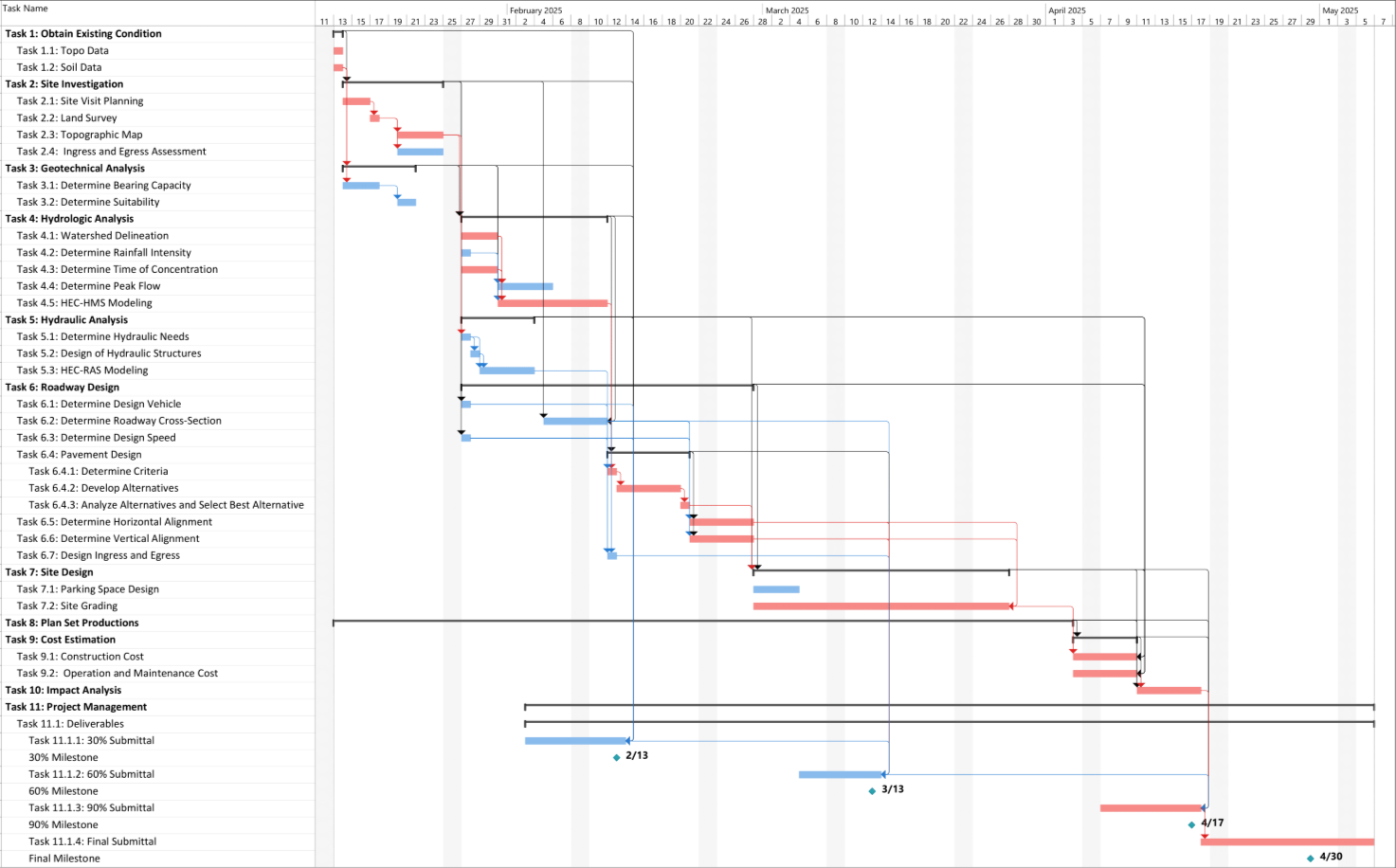
The Gantt Chart below shows the project schedule. The project begins on January 13th, 2025 and all tasks will be completed by May 6th, 2025, for a total duration of 82 days, excluding weekends. Tasks 1-4, 6.1, and 6.3 will be completed for the 30% submittal. Tasks 5,6, and 7.1 will be completed for the 60% submittal. Tasks 7.2 and 8-10 will be completed for the 90%. The Final submittal will be completed by May 6th.

Staffing
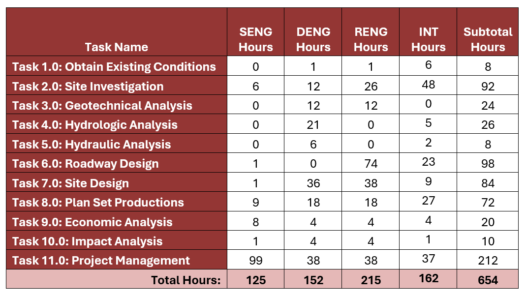
The staffing positions include a Senior Engineer, Drainage Engineer, Roadway Engineer, and an Engineering Intern. The staffing plan provides an overview of who will complete each task, based on varying qualifications, and how many hours each task will take. The total personnel hours required for the completion of this project are summarized in the table below.

Cost of Engineering Services
The total cost of engineering services for the Malabar Winters Campground roadway design is presented in the table below. The cost is subdivided into the personnel, travel, supplies, and subcontracting categories.

