Optimal Load Placement
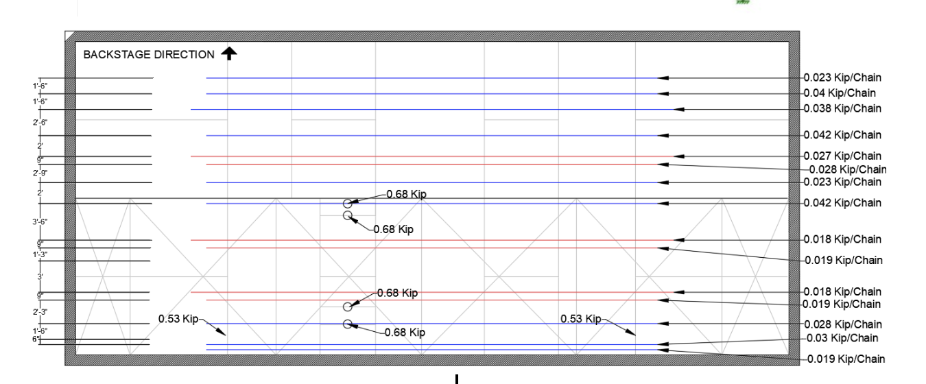
The design decisions for this plan was controlled by the demand/capacity ratio under the ultimate strength rather any deflections under serviceability. This load case has 2000 lb loads at 8 different points on the rigging, totaling 16,000 lbs of loading. These load placements are located at exactly 3 feet away from the masonary wall at both sides. This decision was made to mitigate the stresses being added onto the truss, to keep additional stresses within 5%. Figure 26 shows the unity check for this loading plan under load case 1.


