Project Information
Identification of Erosion Source
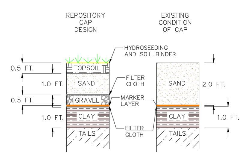
Based on the analysis performed in this project, the source of erosion is most likely due to the composition of the top layer of the cap. The analysis performed by MARS Consultants found that the top two feet of the cap is composed primarily of sand, with no topsoil or drainage layers as specified in the original design. The sand performs adequately as an infiltration layer, but without a gravel layer there is nothing to convey the infiltrated water out of the cap. Additionally, sandy soil is a poor growth medium, so the absence of a topsoil layer is likely why the initial hydroseeding failed. A comparison between the original design and the observed design can be seen below.

Our analysis shows that the geometry of the cap, runoff from the adjacent hill, and the shear strength of the soil do not significantly contribute to erosion of the cap. Details of this analysis can be seen in the final design report.
Constraints
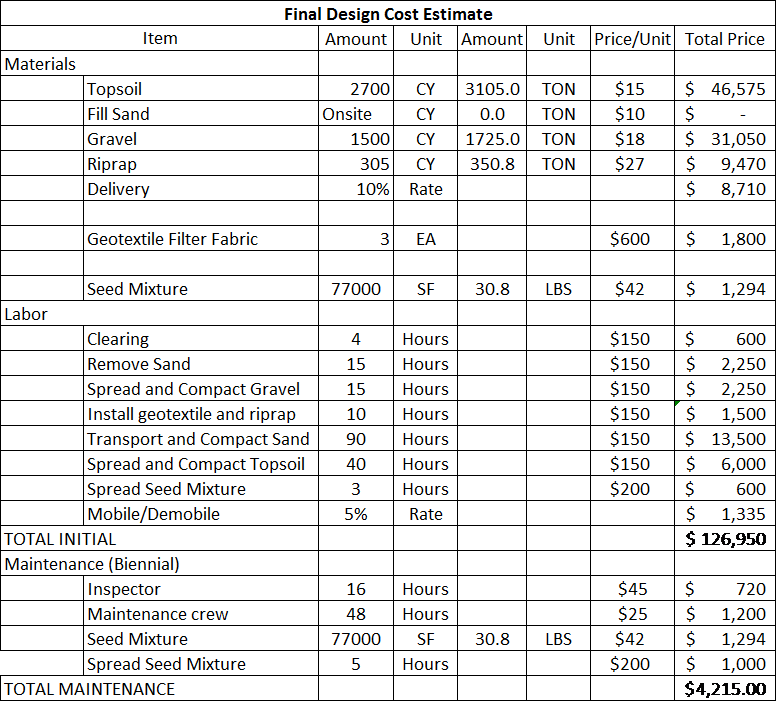
The main constraint for this project was price. The BLM was unable to support any project with an initial capital cost of over $200,000. In order to meet this constraint, MARS Consultants opted to recycle materials wherever possible in design alternatives to reduce material and transportation costs.
Design Alternatives
Three possible design alternatives were created by MARS Consultants. A description of each design can be seen below.
-
For this design, the sand from above marker layer of cap will be removed. Create a three layered system that would include, starting from the lowest layer, a 6 in. gravel drainage layer, a minimum of 6 in. transition layer composed of the sand that is currently above marker layer, and an 8 in. layer of topsoil. Gradation for soils for the drainage layer and topsoil layer gradations will be chosen to create adequate bridging between the layers to reduce infiltration of the upper layers into the lower. The geometry of the cap will be altered to decrease the slope as far as possible by using the transition layer, with maximum sloping of 4.5:1. Native grass seeding will be spread across the entire cap to promote vegetation.
-
This design alternative also involves excavating the top layer of the cap (above the marker layer). The excess material would be used to reshape the geometry of the cap. The new cap geometry would direct runoff into three rip-rap channels on the cap to assist with drainage during large storm events. A gravel layer would also be installed under the sand layer to further facilitate drainage. A 12-inch topsoil layer would be placed on top of the sand layer to provide a suitable growth medium for hydroseeding.
-
This design involves leaving the cap as it is currently and add a layering system on top of it beginning with a 6” clay layer, the clay layer will be topped with an orange construction fencing to mark that layer. The clay layer is followed by a 1ft. gravel layer with a 4 in perforated pipe (6 pipes), a 1.0 ft. sand infiltration layer, and a 6” topsoil layer with hydroseeding on top. The cap geometry will be altered to direct drainage into the areas with perforated piping.
Each design was evaluated based on initial cost, maintenance costs, aesthetics, and maintenance. As can be seen in the decision matrix below, Alternative 3 received a low score due to its high initial cost. Alternative 2 was chosen because it was discovered that the average side slope of that design was the same as the slope called for in Alternative 1, meaning that it would perform the same in that regard.
Final Design
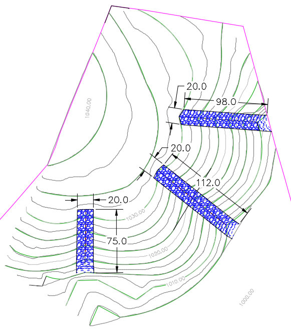
The final design specifies three rip-rap channels on the cap, located where the worst erosion was observed. The excess sand is used to alter the geometry of the cap to create these channels. The design specifies a 6 inch gravel followed by a sand layer of varying depth to achieve the desired geometry. 12 inches of top soil is placed on top of the sand to provide a growth medium for the hydroseeding. Renderings of the final design, typical channel cross section, and layering details can be seen below.

Channel Cross section

Layer Details

Cost Estimate
