Concept Generation:
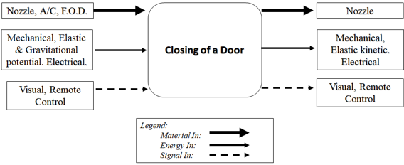
Black Box Model.
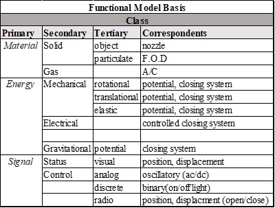 Functional Basis Model.
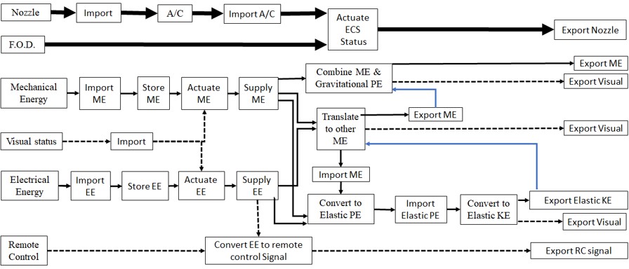 Functional Decompositional Model.
Decision Matrices:
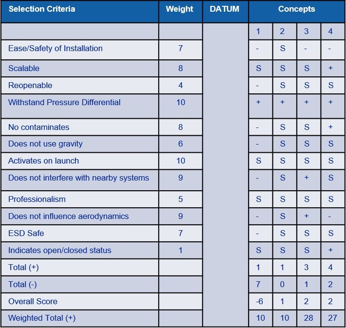 Pugh chart.
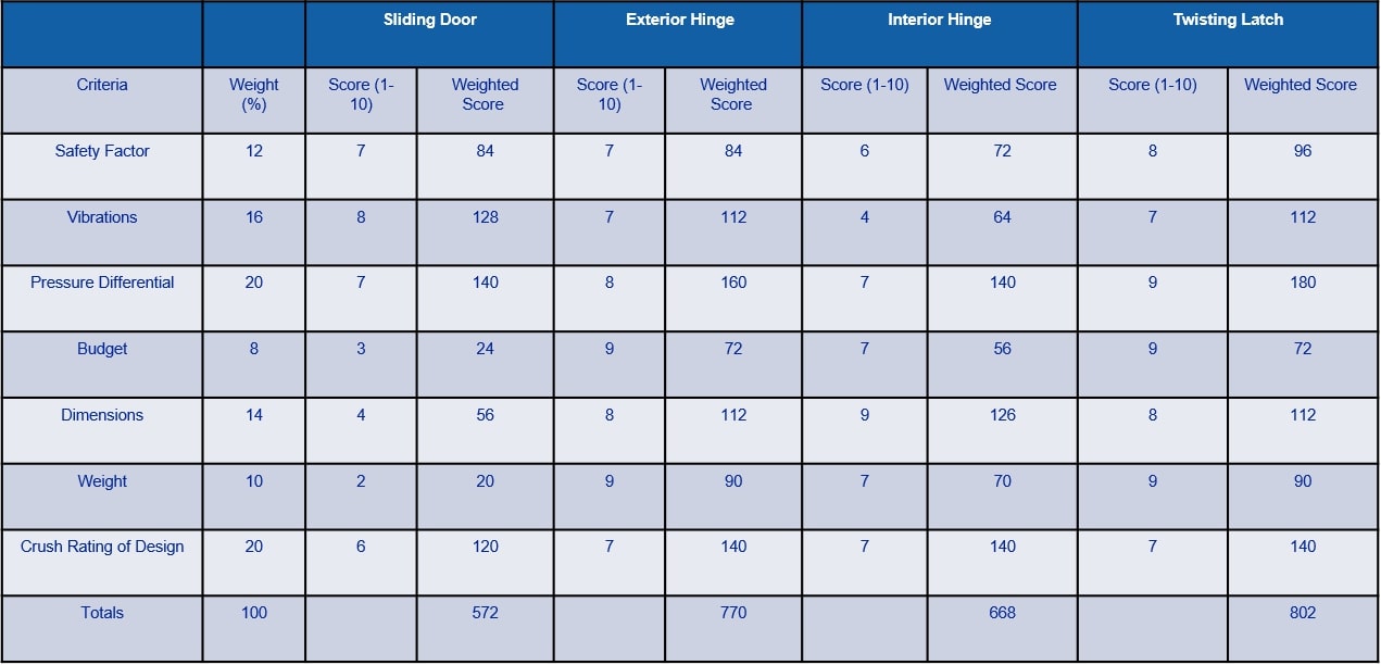
Decision Matrix.
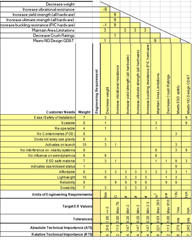 House of Quality, QFD.
Preliminary Design: (opened)
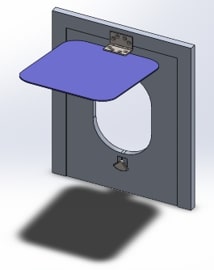
Full external view.
Cut,full view of bottom of the housing.
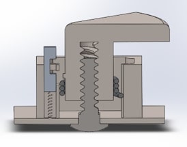
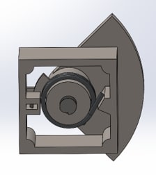
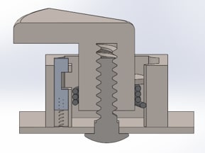
Cut, full lateral view.
Lateral section latch view
Preliminary Design: (closed)
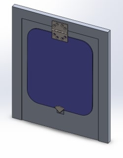
Full external view.
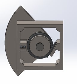
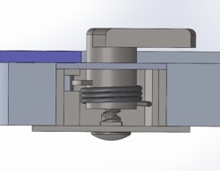
Cut,full view of bottom of the housing.
Cut, full lateral view.
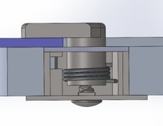
Lateral section latch view
Analyses/Validation:
Weight analysis table.
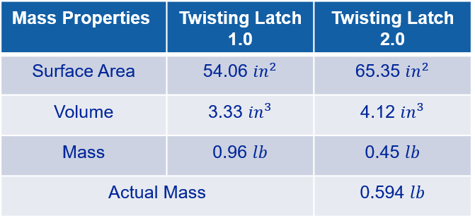 Weight analysis table continued.
Quarter circle wng thickness analysis.
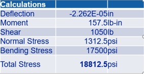
Quarter circle wng thickness analysis.
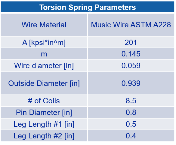
Torsion spring design parameters table.
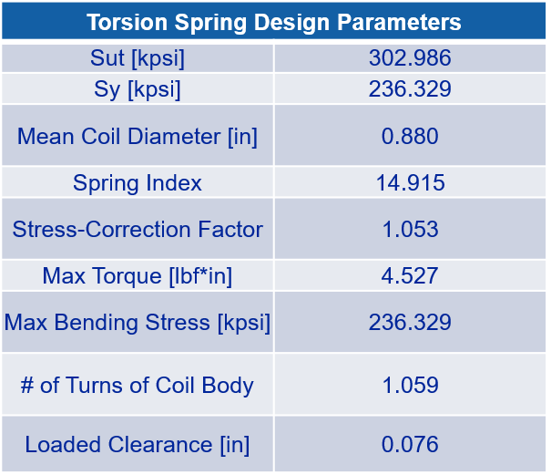
Torsion spring analysis table.
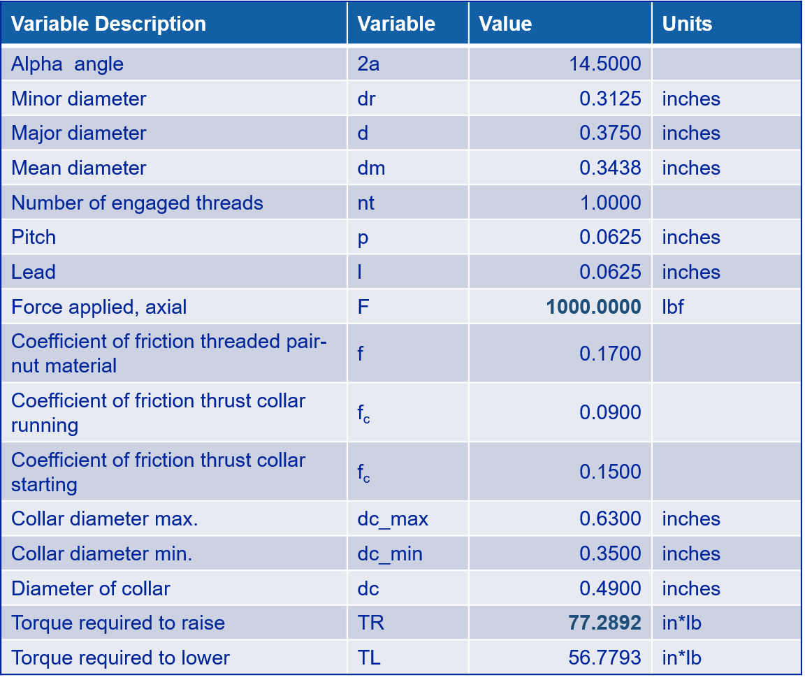
Excel calulator results on threads analysis.
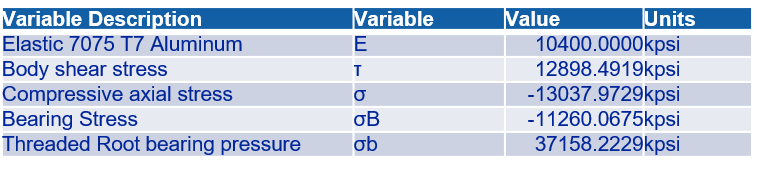
Excel calulator results on threads analysis.
3D Proof of Concept:
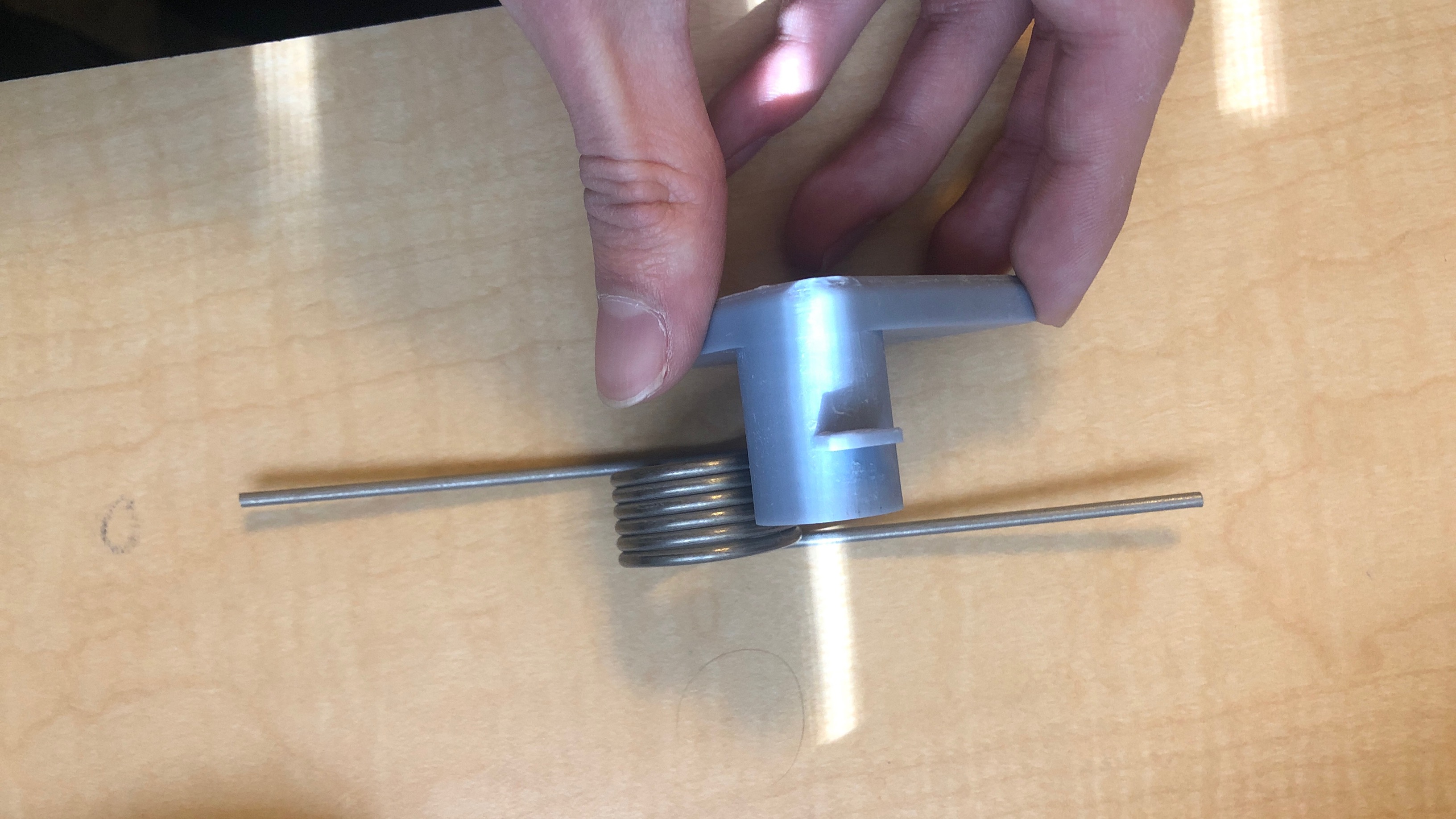
Image: Torsion spring configureation on 3D shaft.
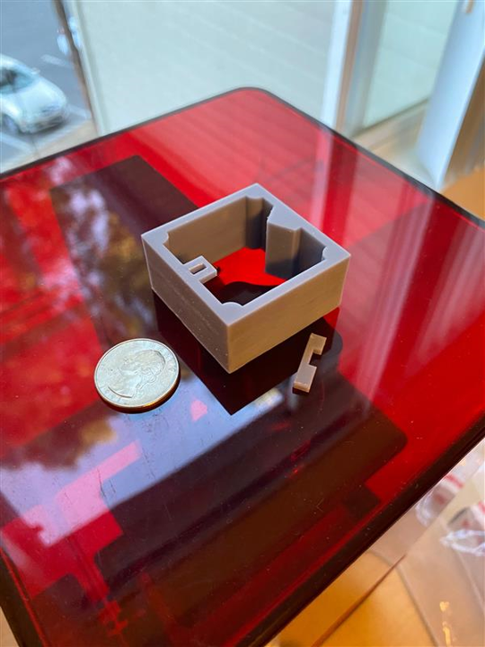
Image: 3D resin printed housing.
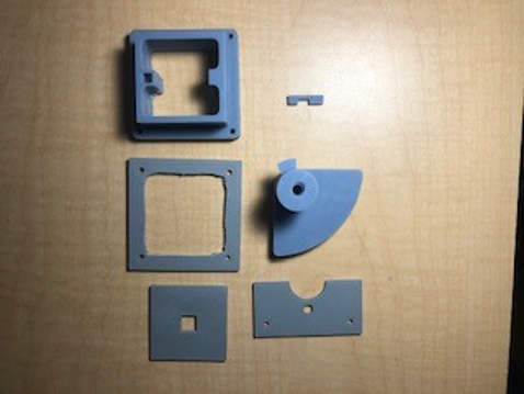
Image: All 3D resin printed parts.
Machine Shop:
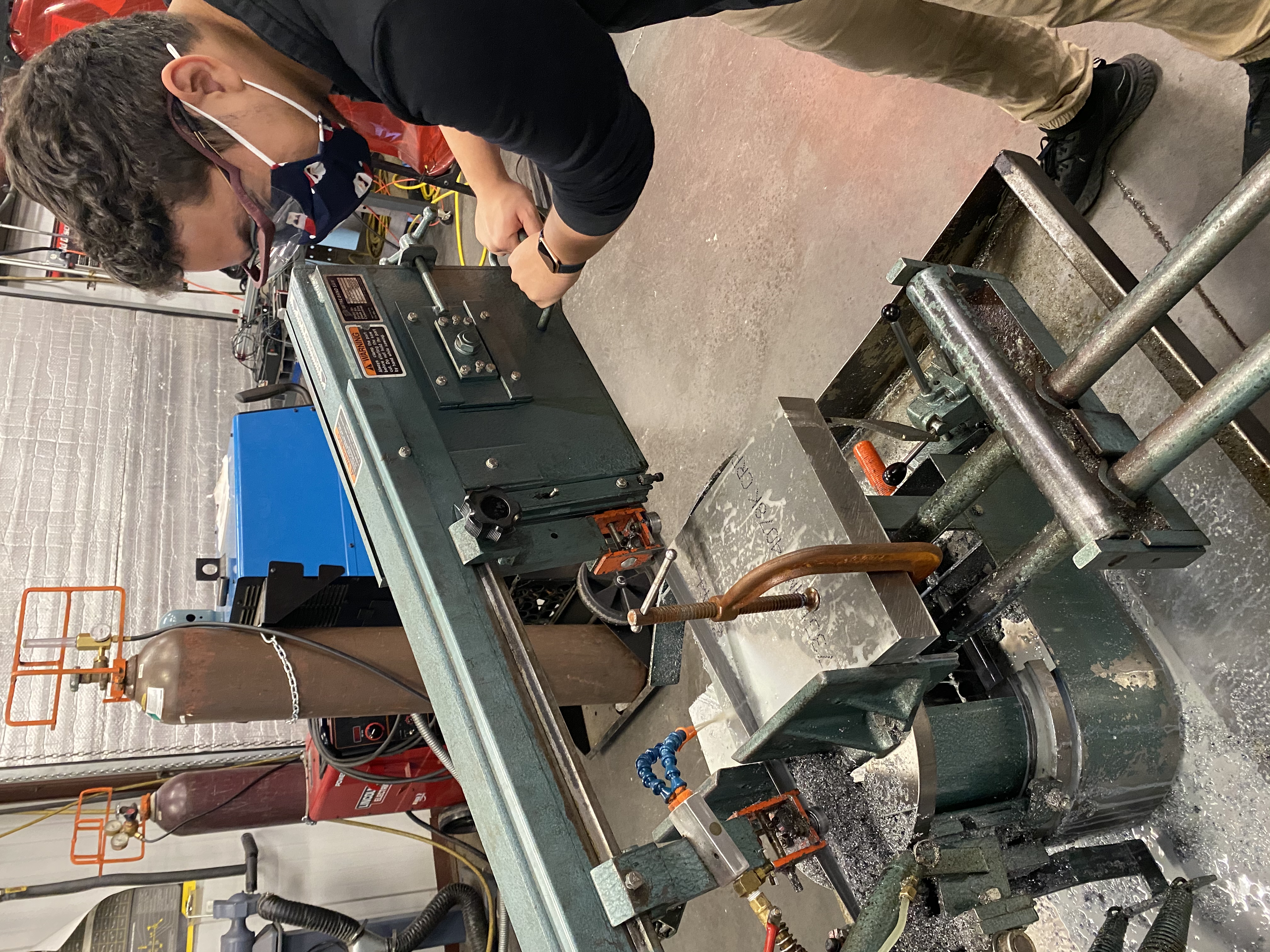
Image: Cutting material to size.
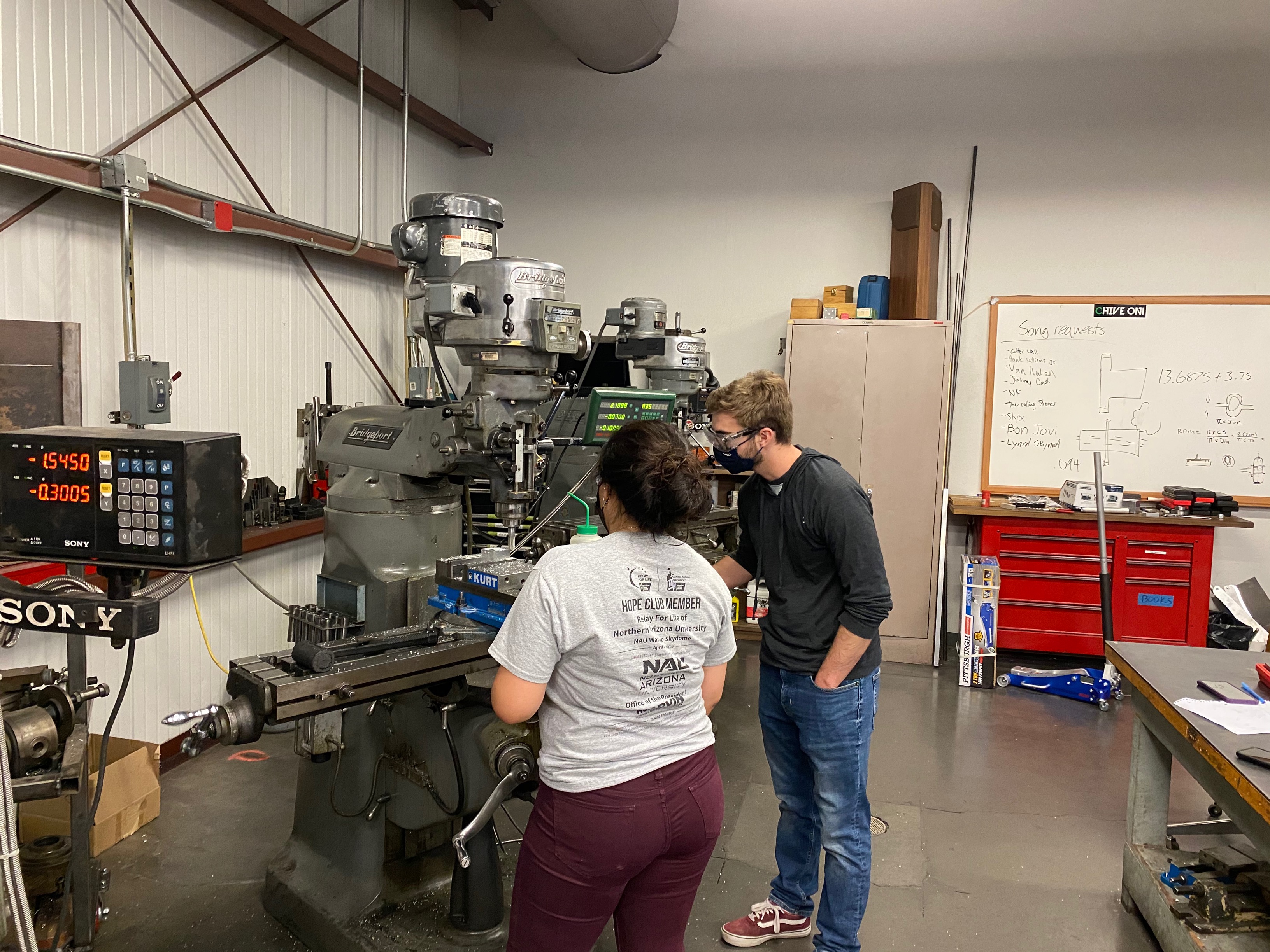
Image: Milling work on shaft.
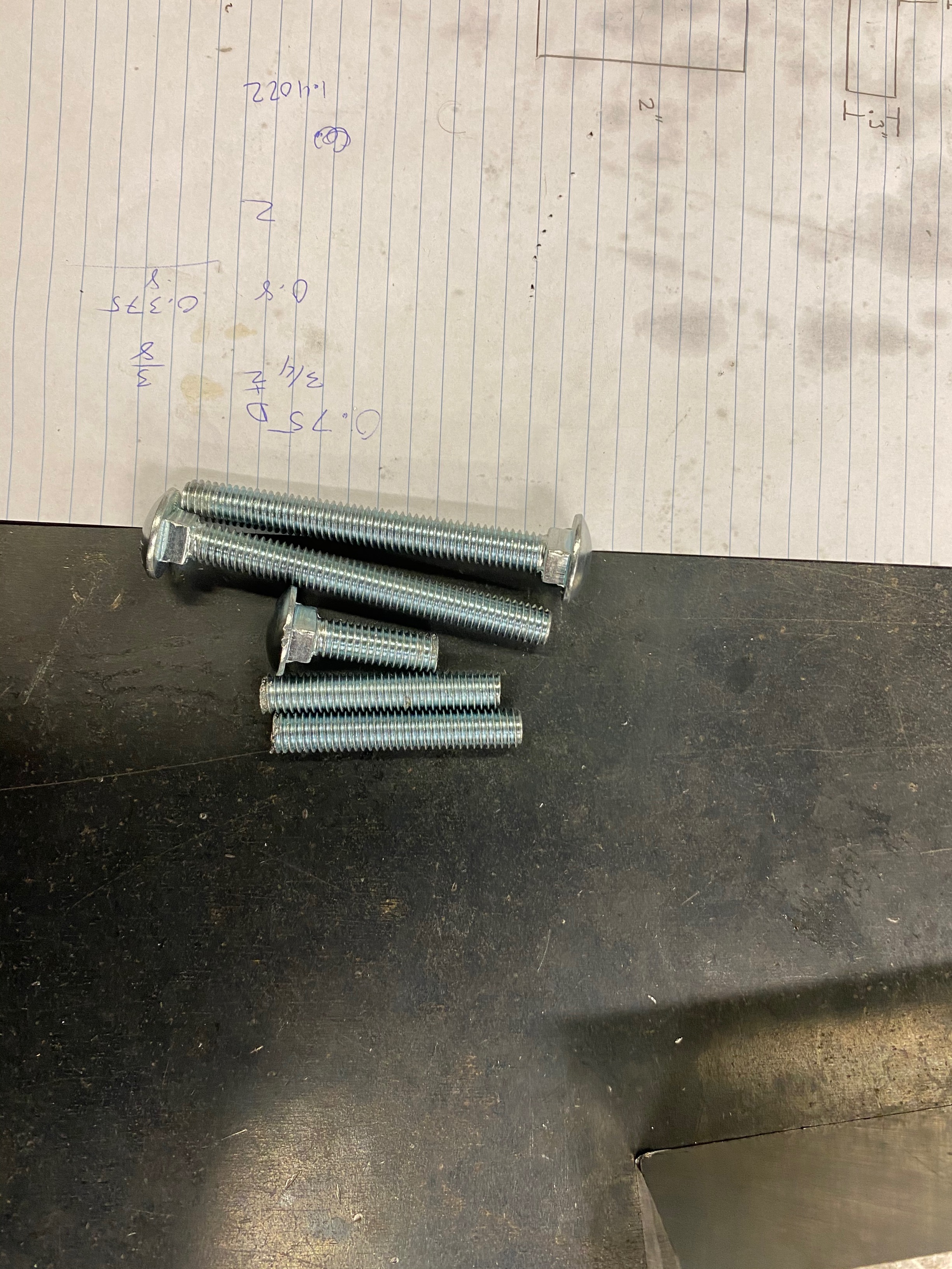
Image: Bolts cut to 1in" and spares.
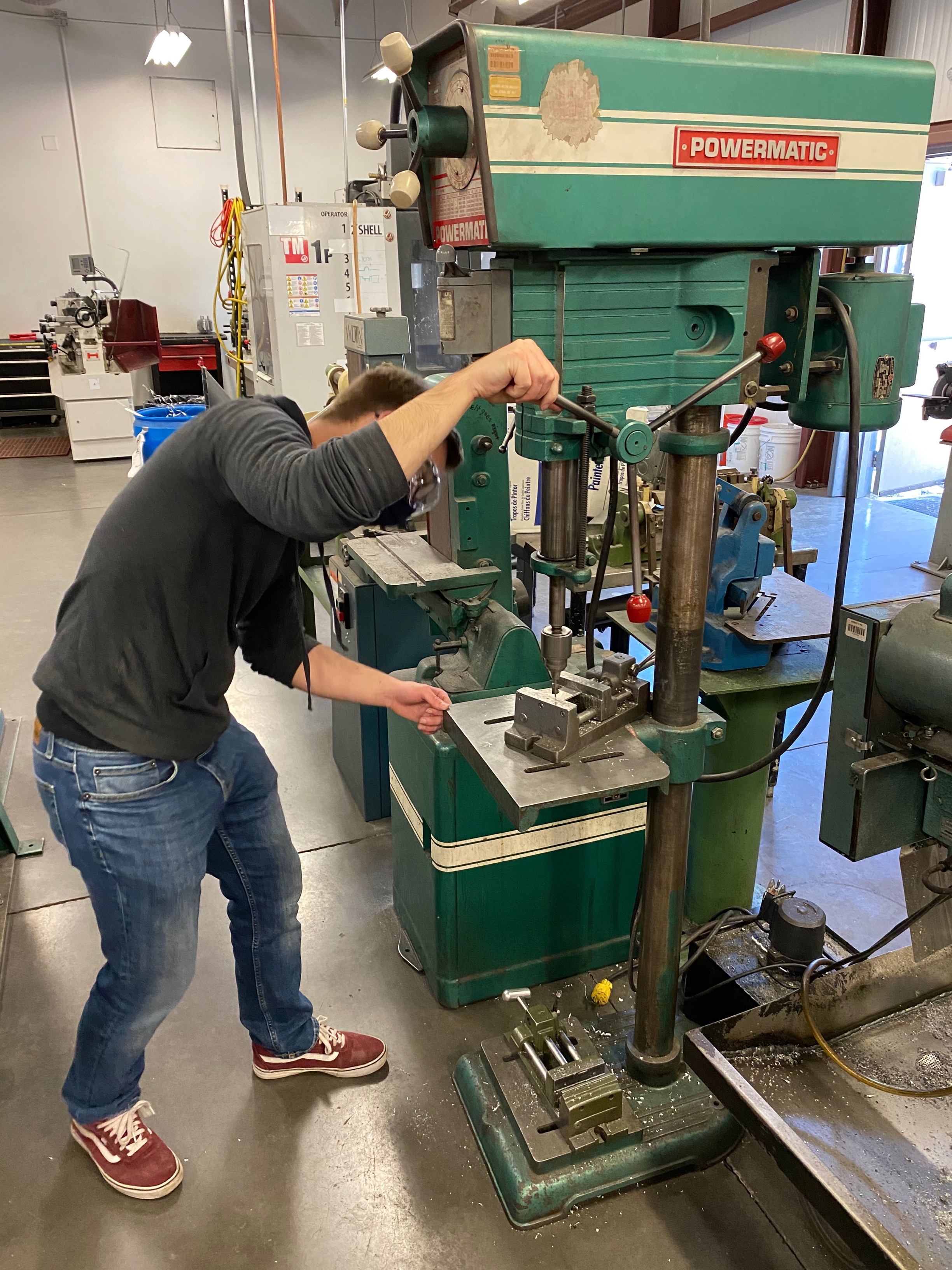
Image: Addition of holes to plates.
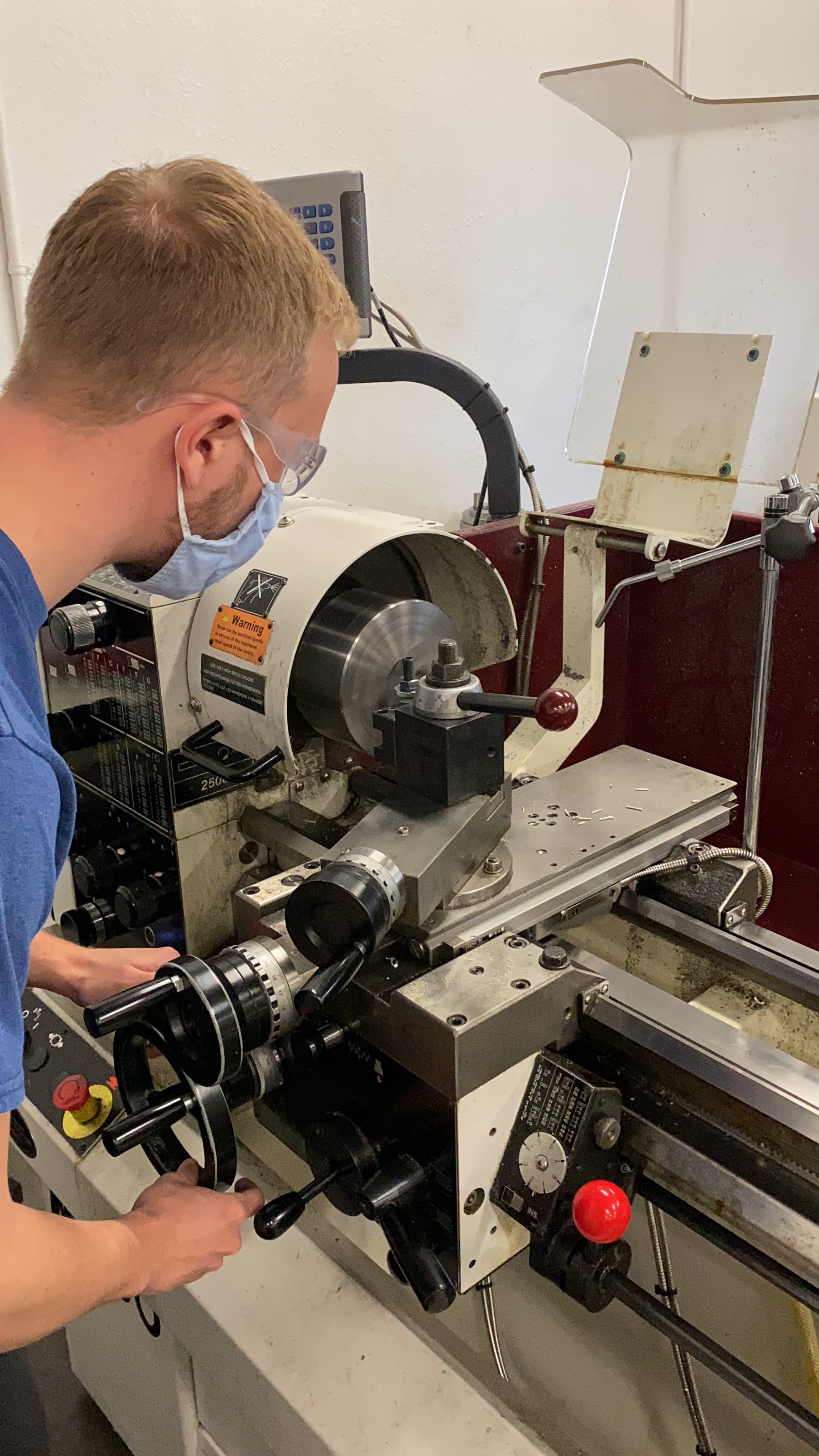
Image: Lathe work for pin.
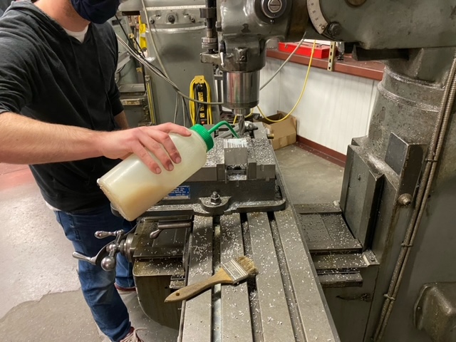
Image: Milling work.
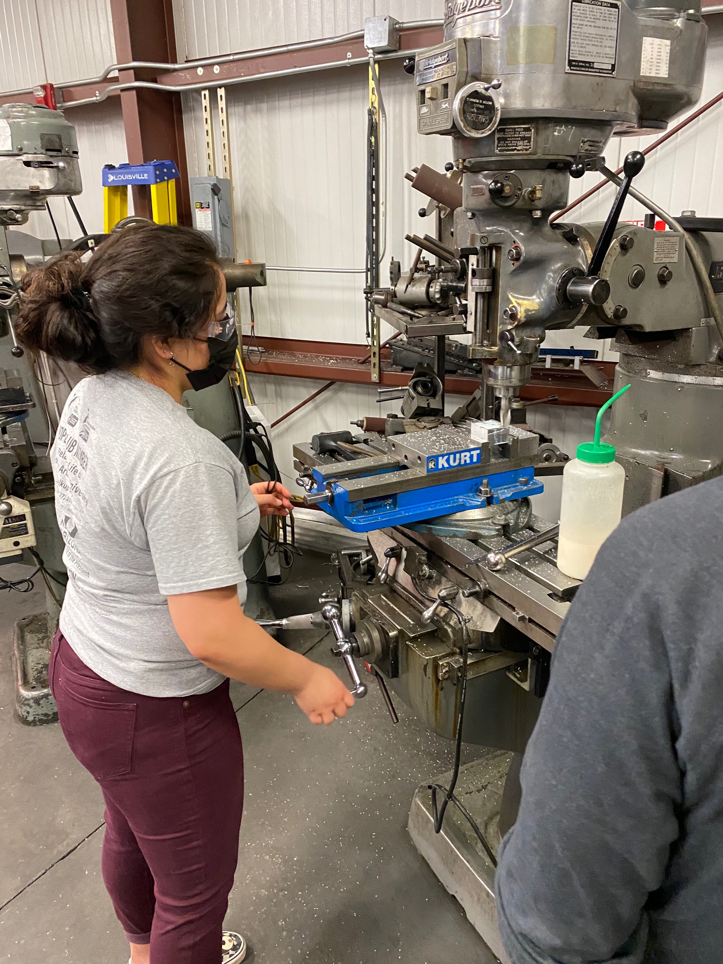
Image: Milling work on shaft.
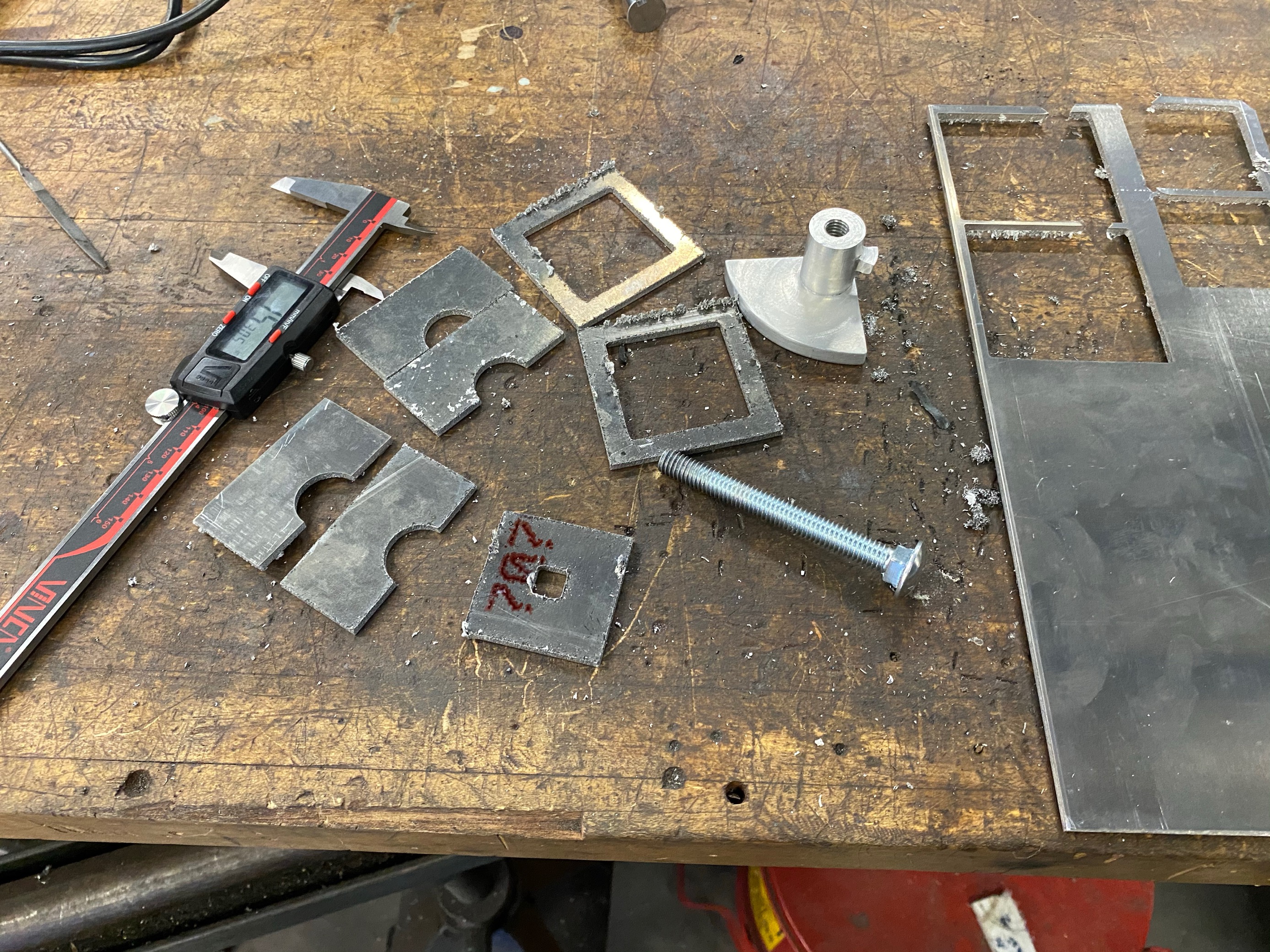
Image: Results of CNC plasma cutting table.
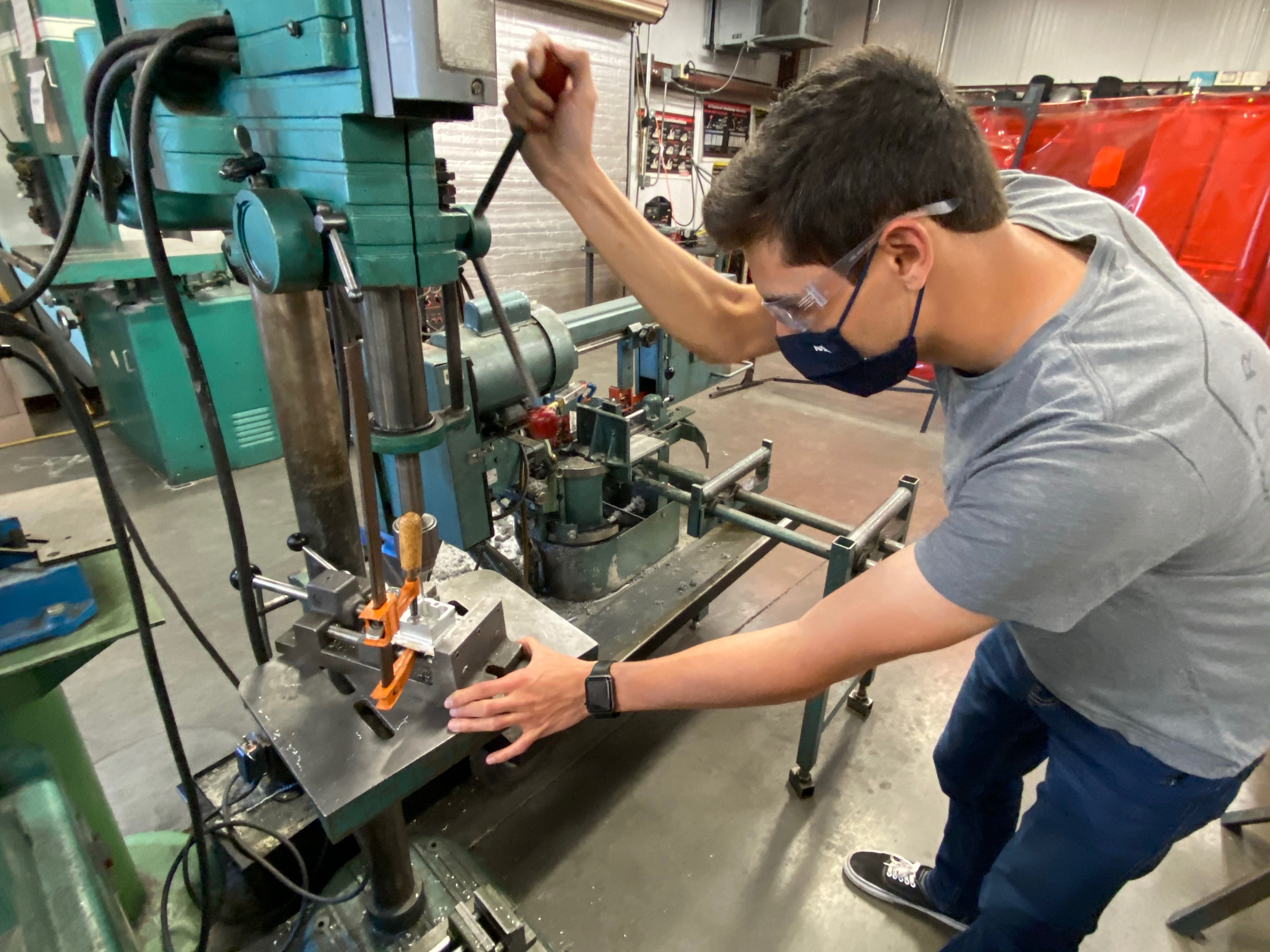
Image: Addition of holes to plates.
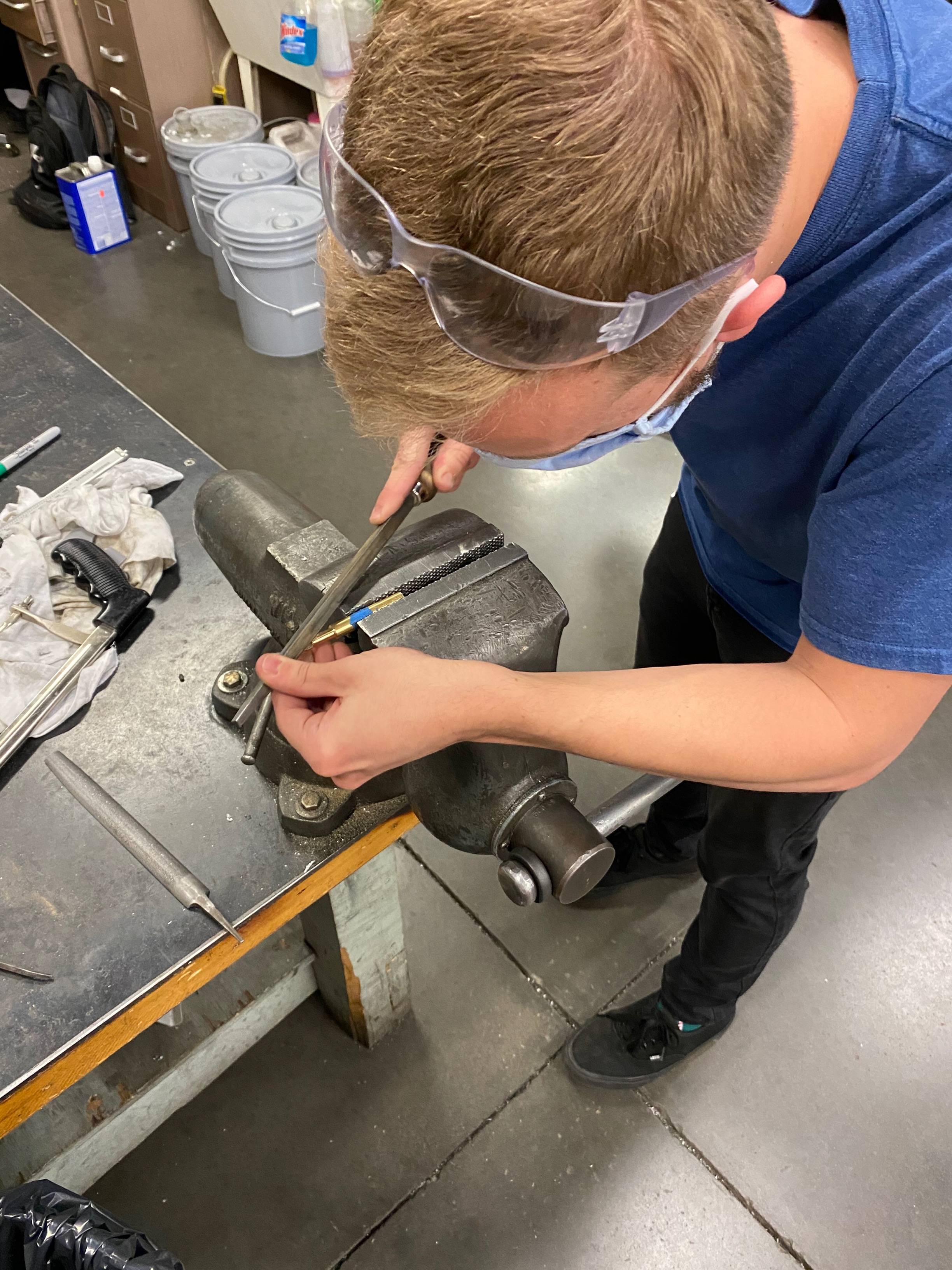
Image: detail work on pin manufacturing.
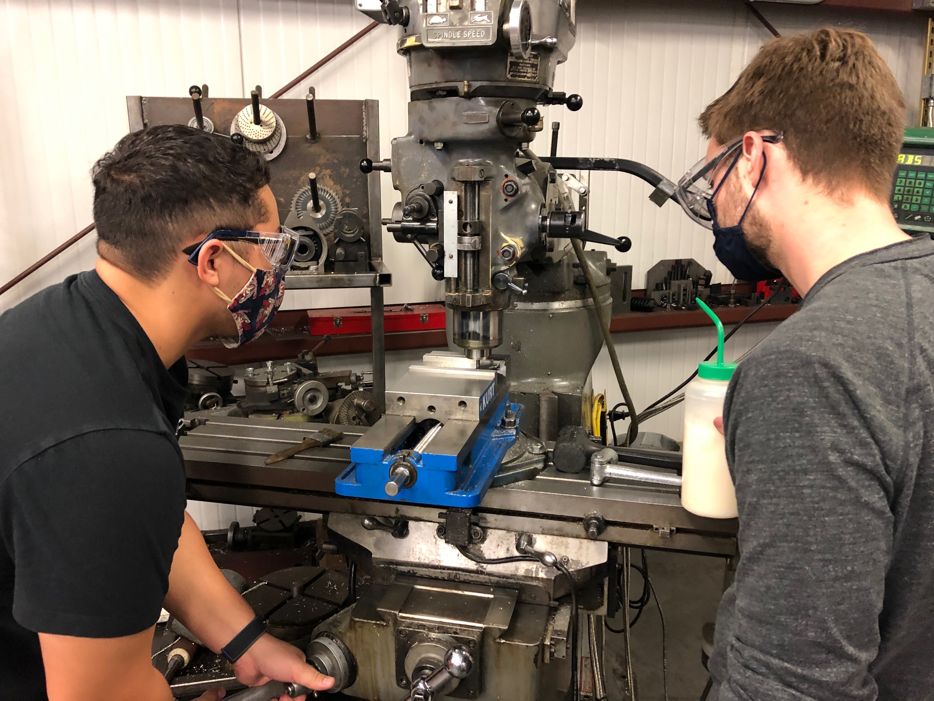
Image: Millling work continued.
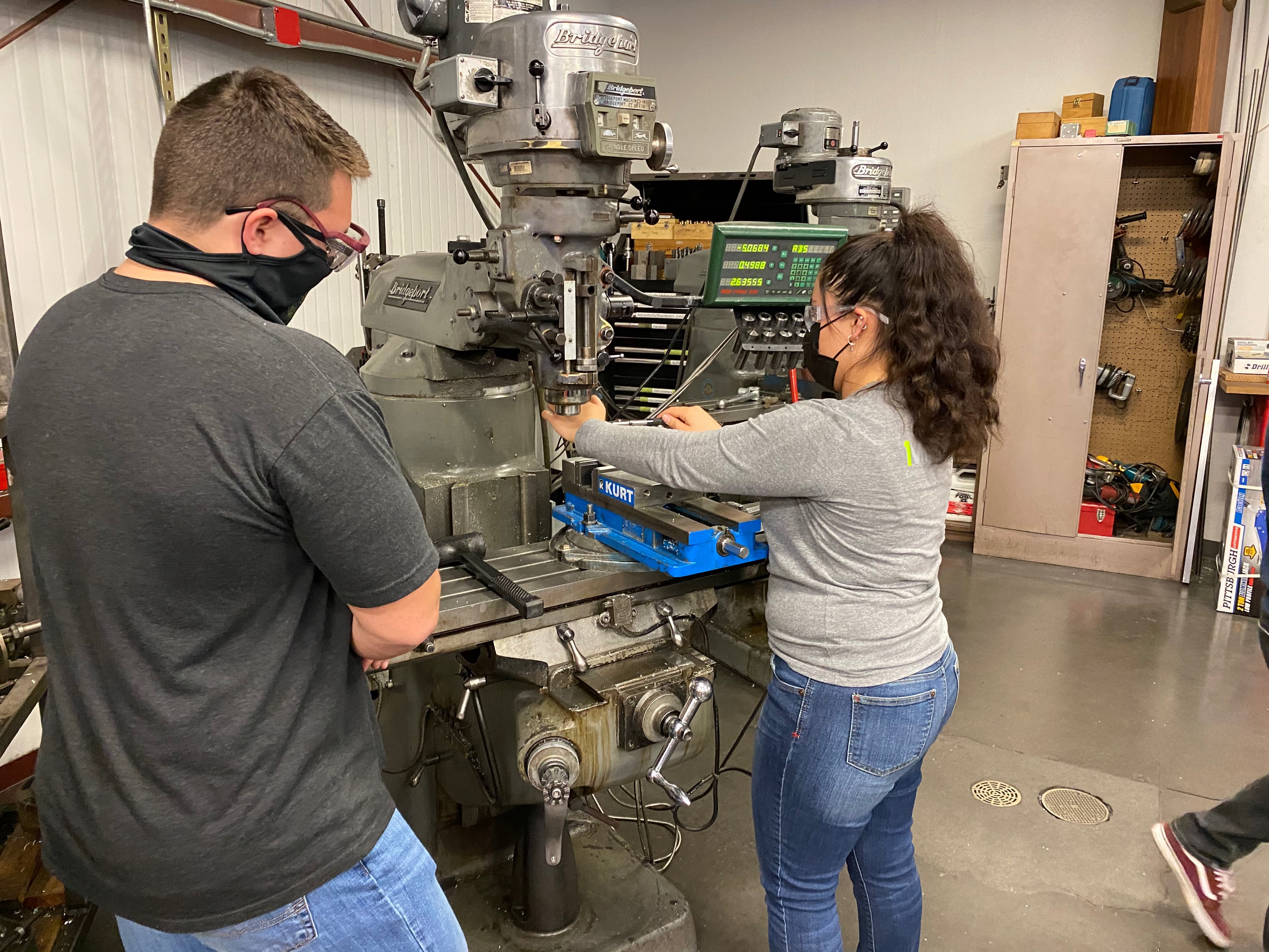 Image: Milling work on shaft continued.
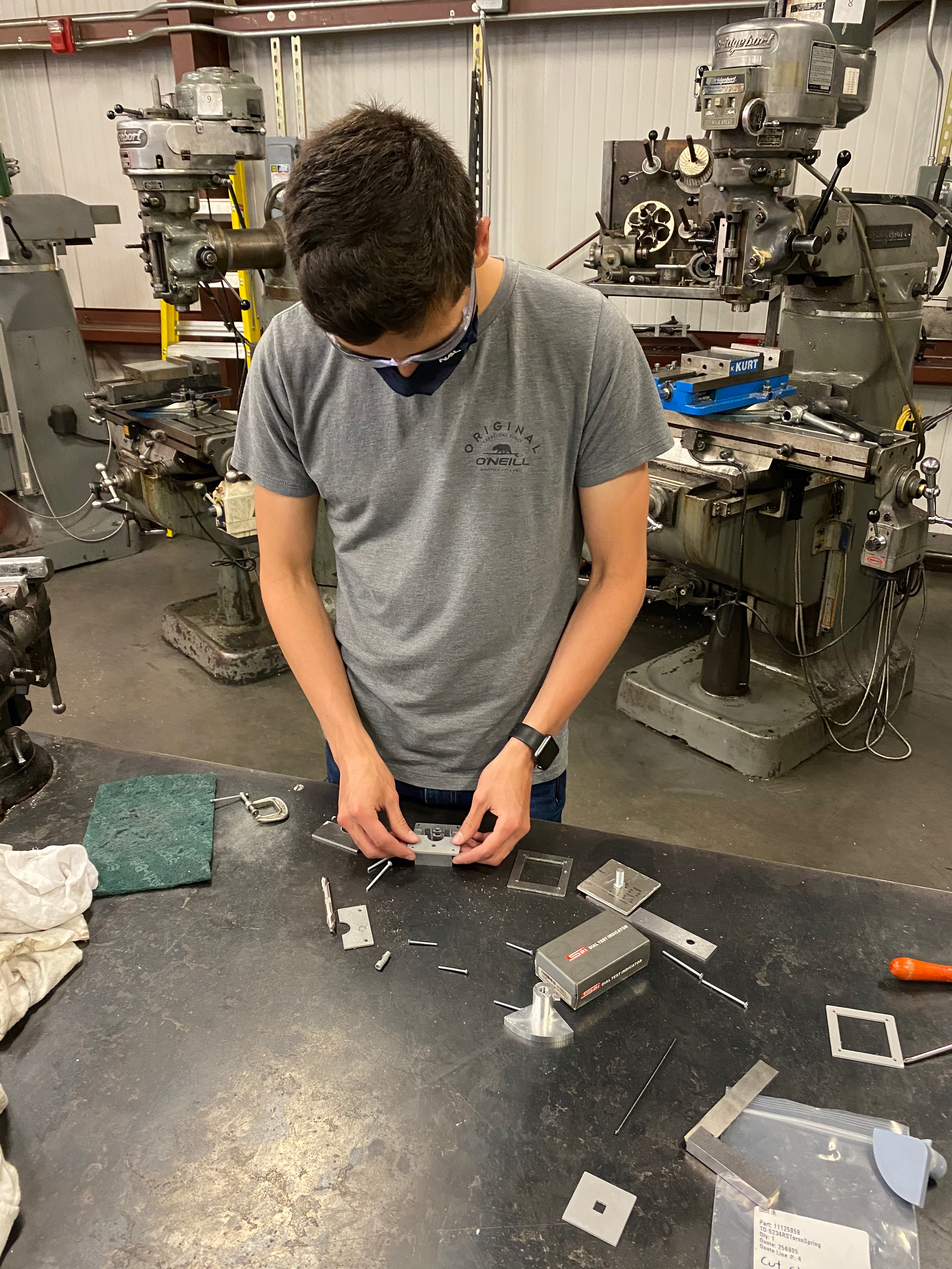
Image: Detail filing on plates.
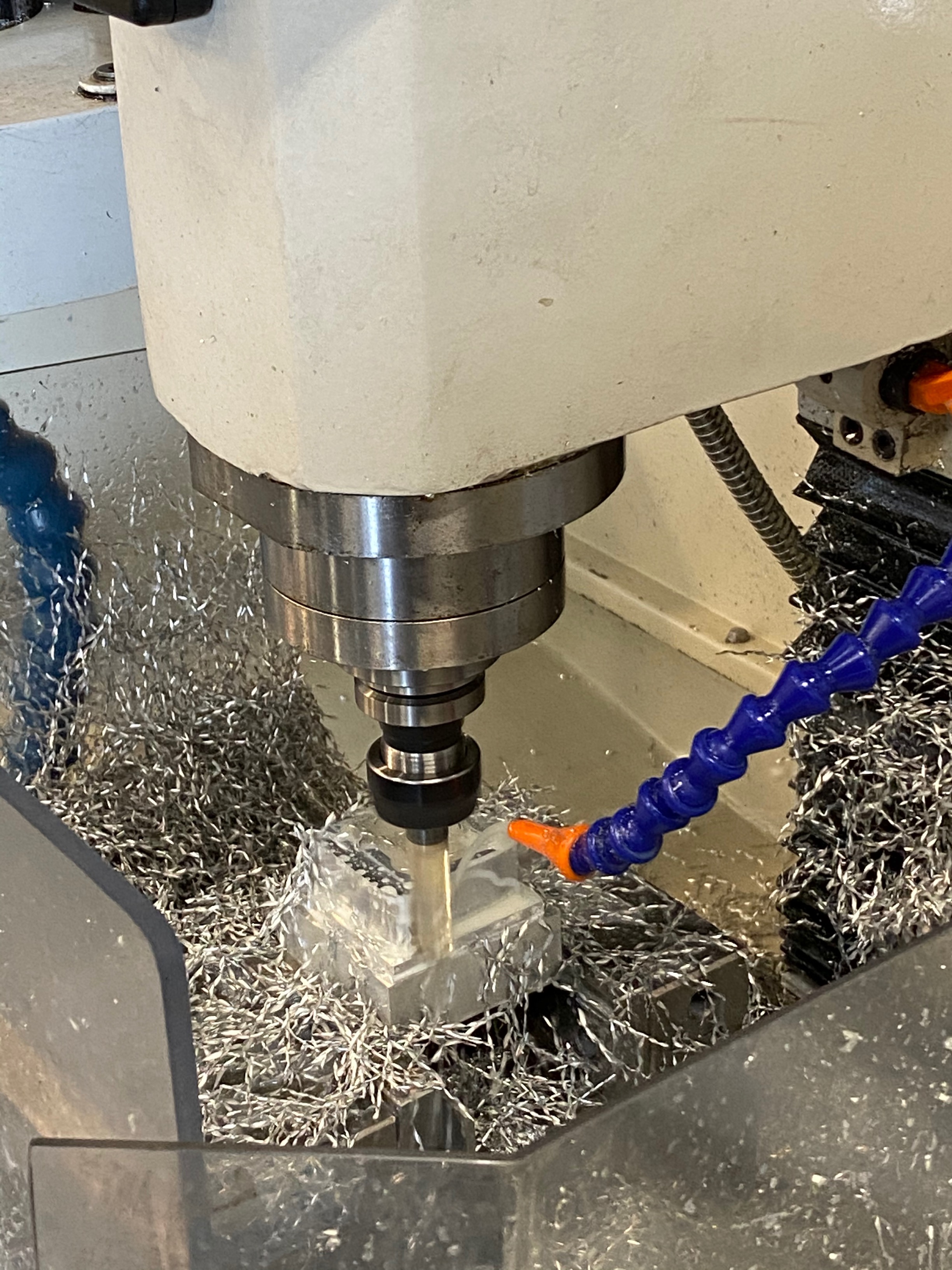
Image: CNC of the housing in progress.
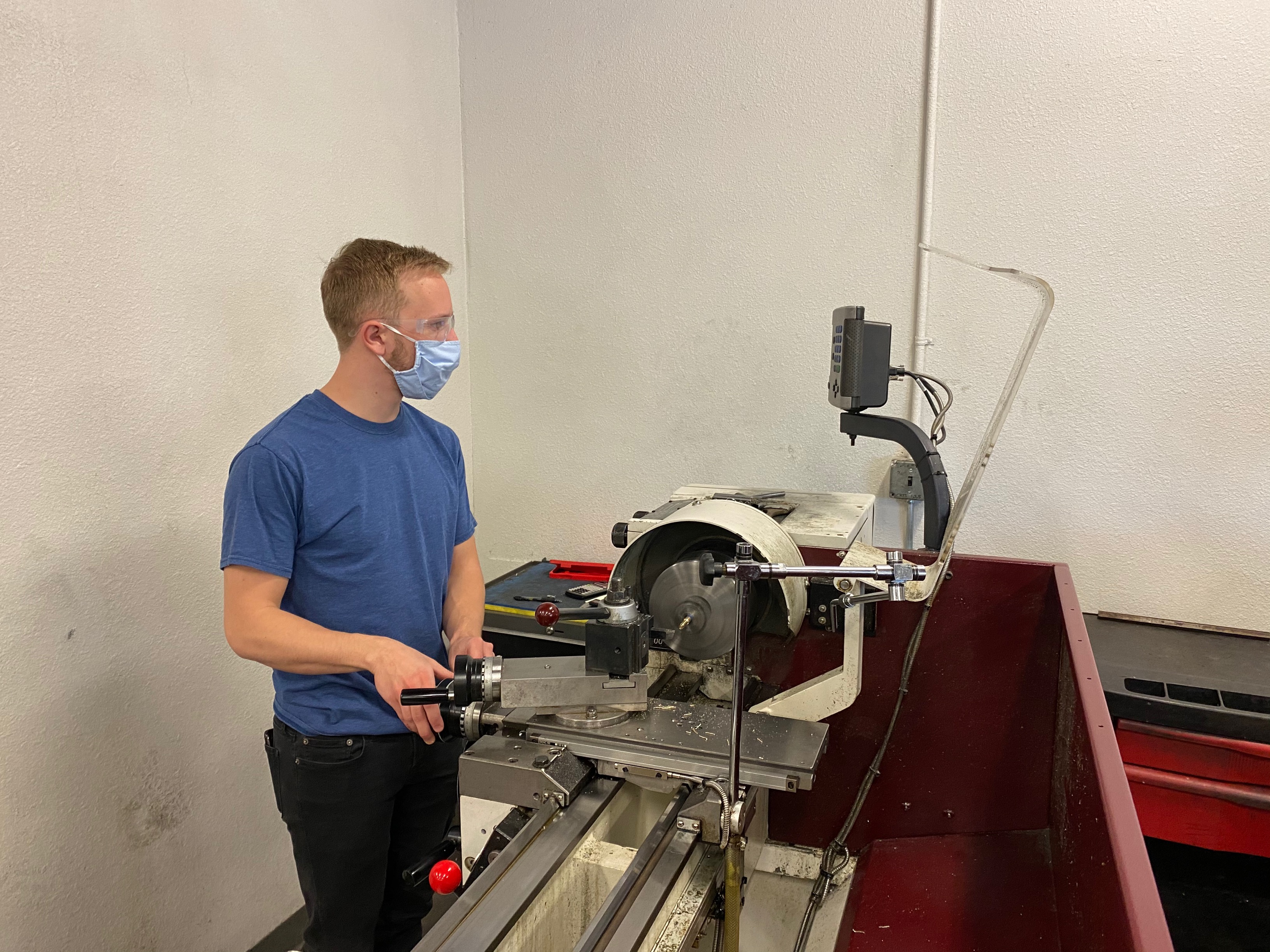
Image: Lathe work on pin continued.
Process:
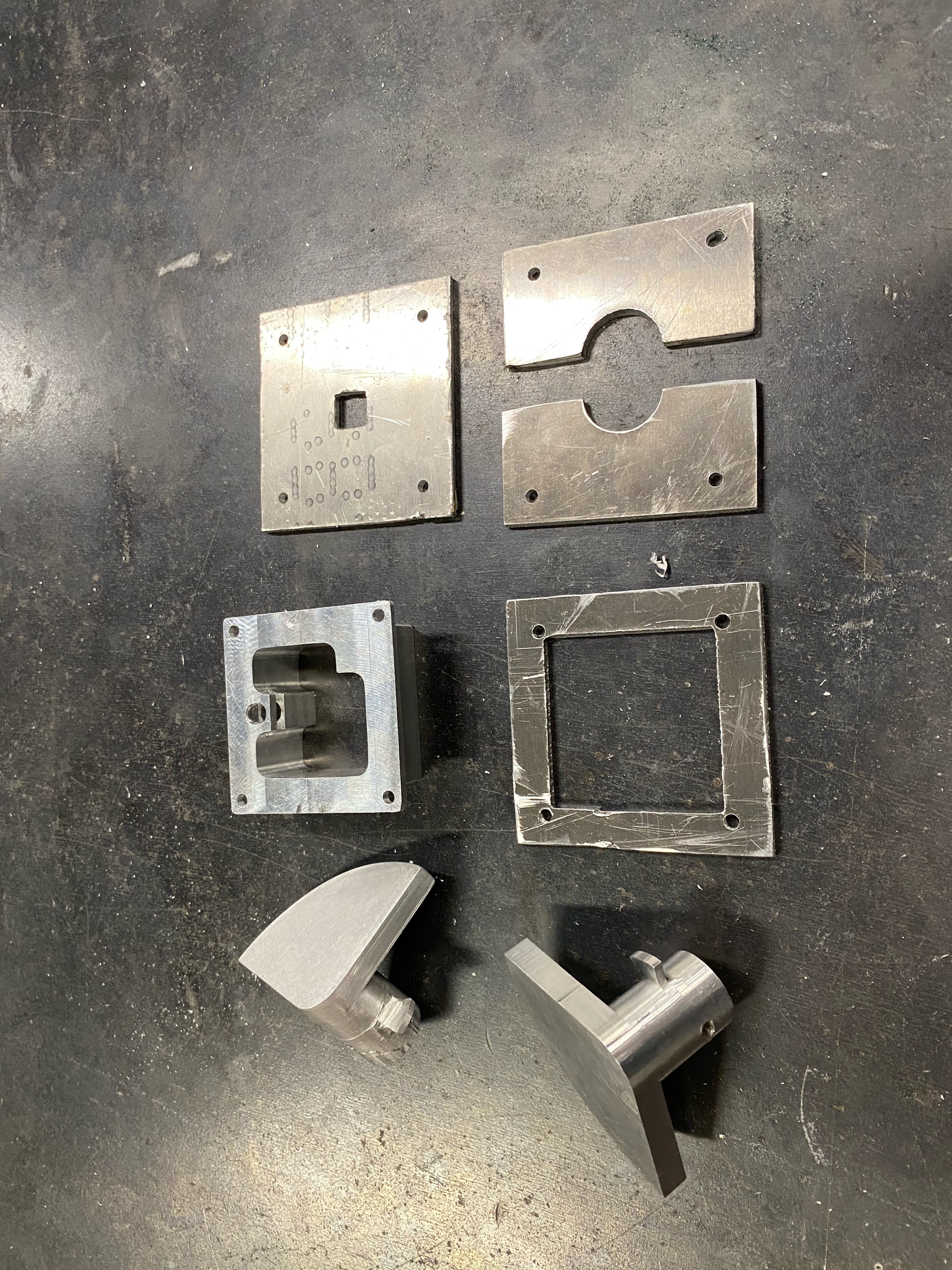
Image: Plates and shafts.
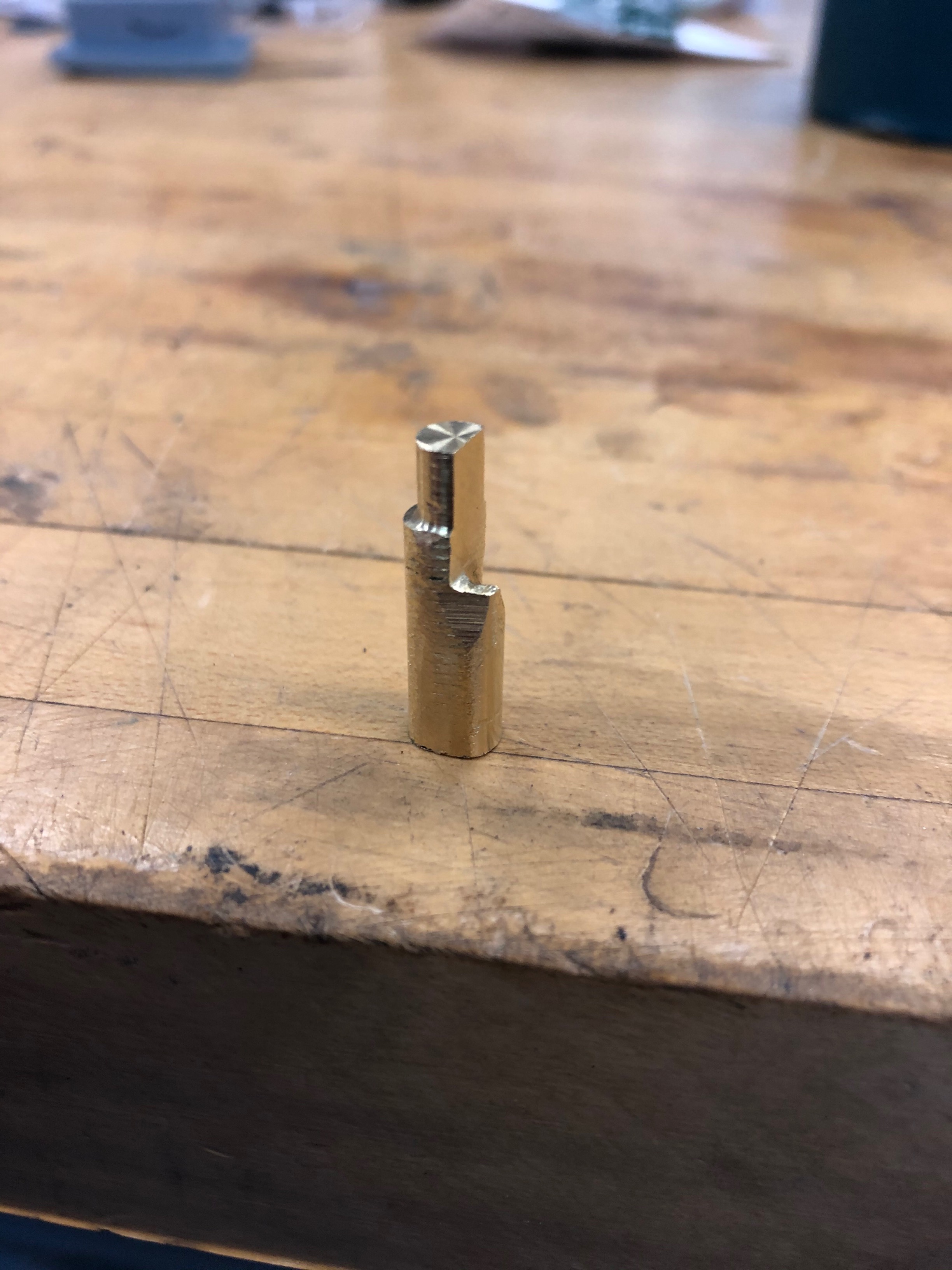
Image: Manufactured pin.
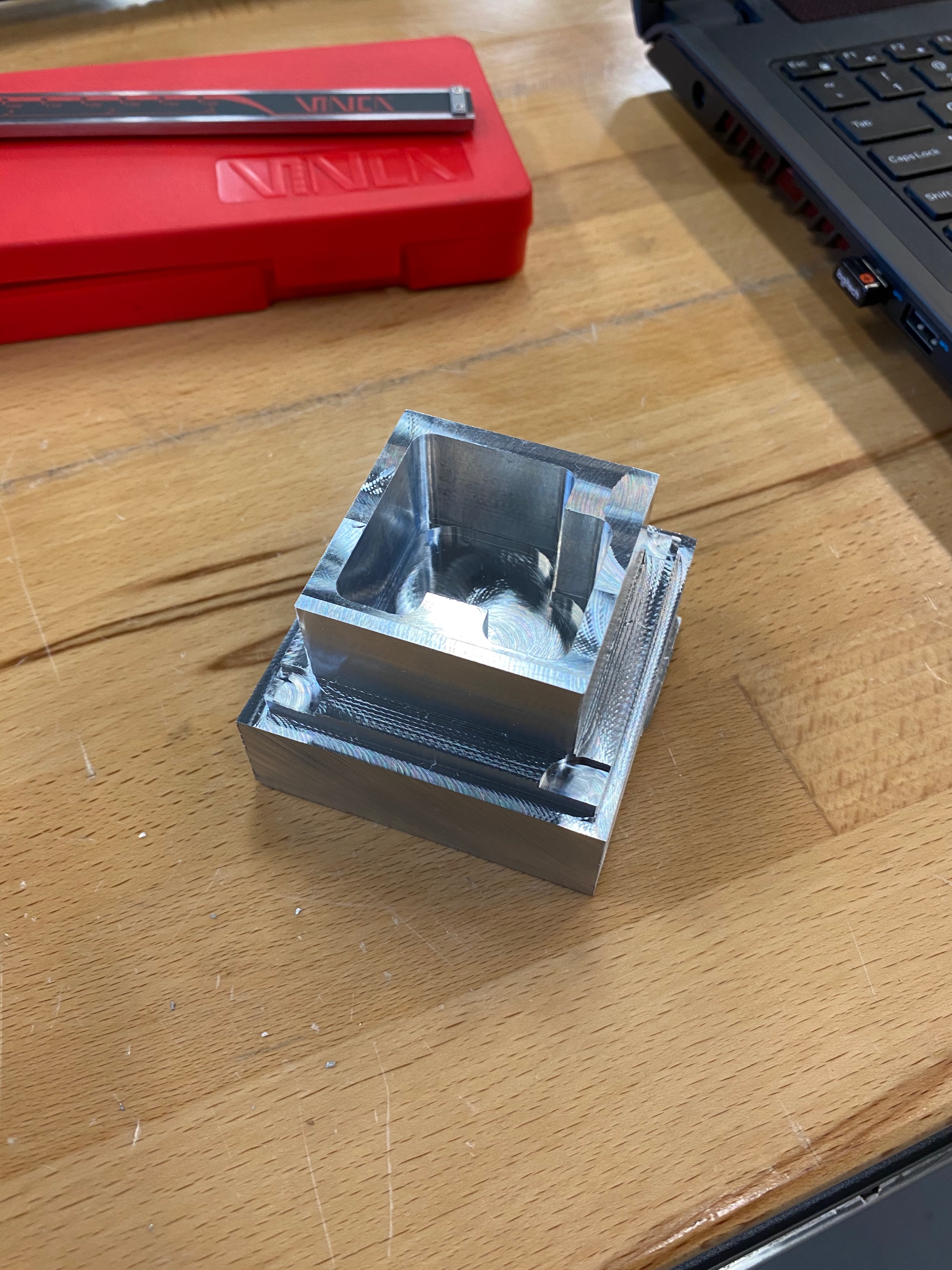
Image: Tormac housing in process.
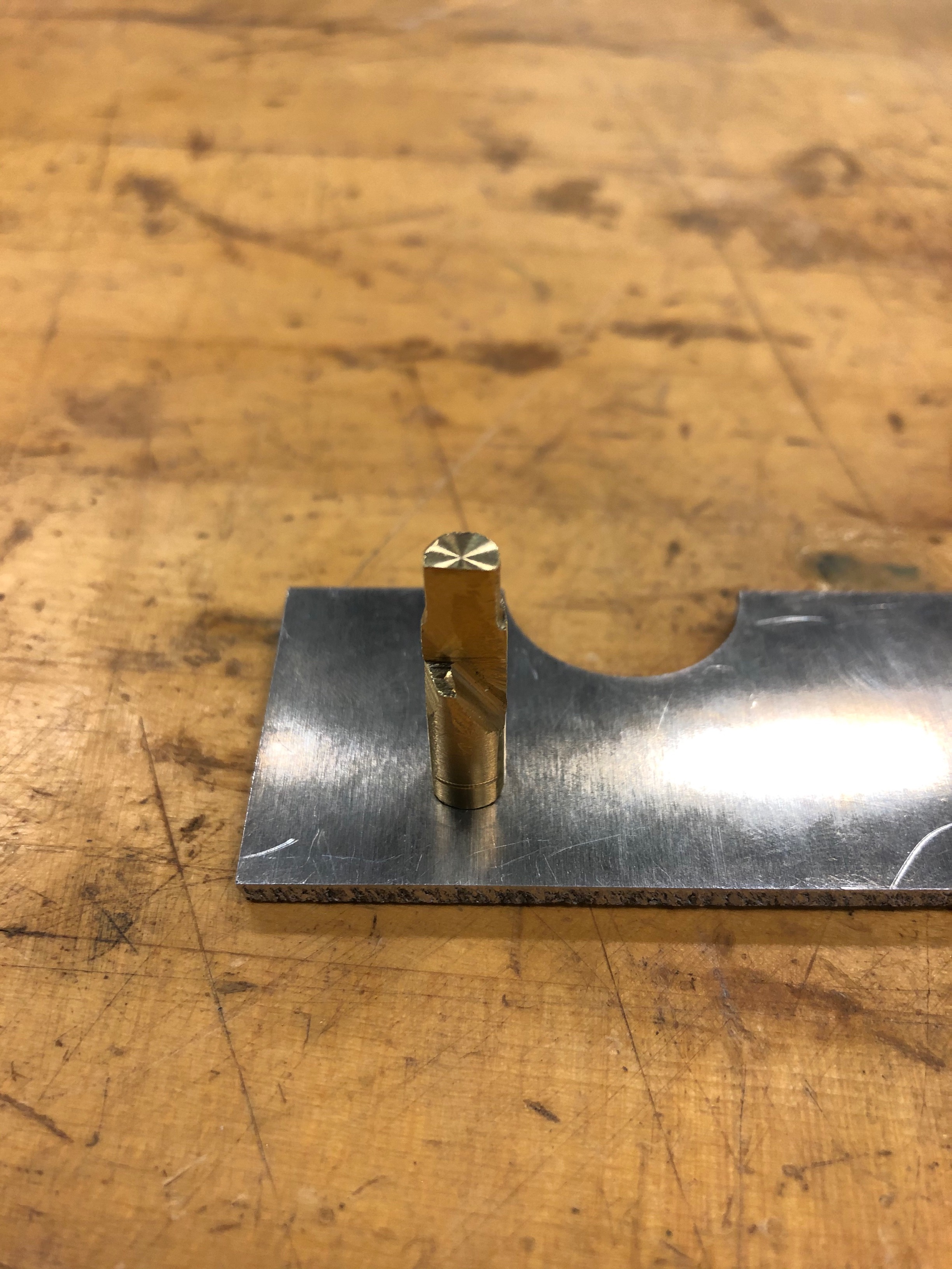
Image: Pin in top plate.
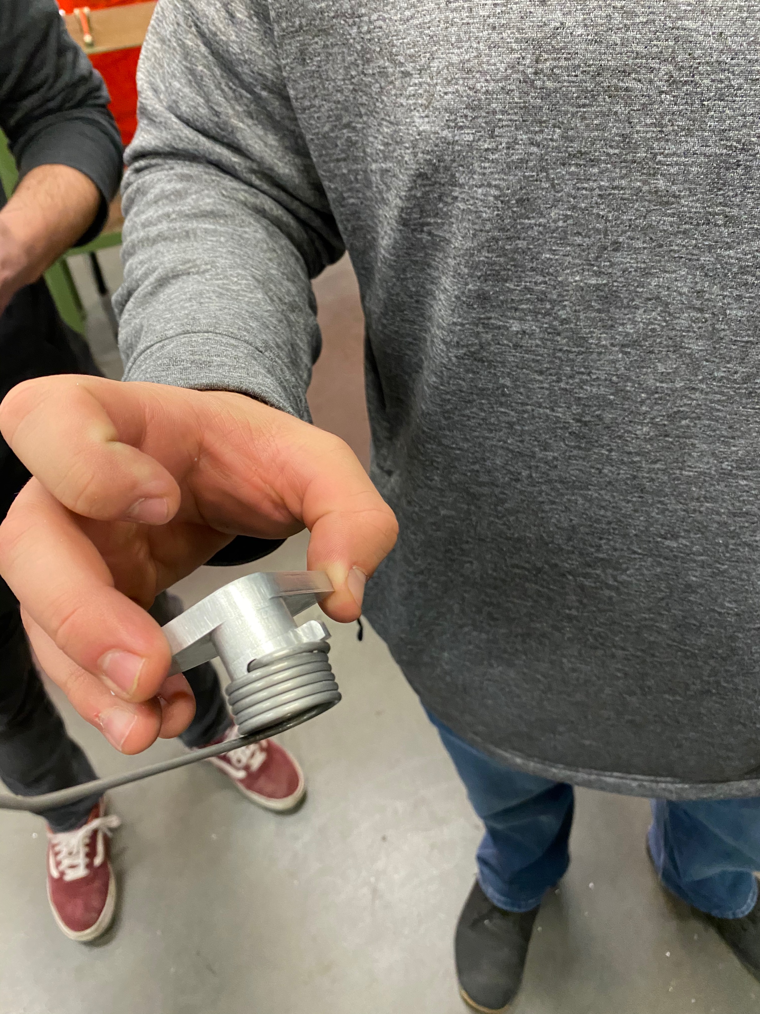
Image: Torsion spring added.
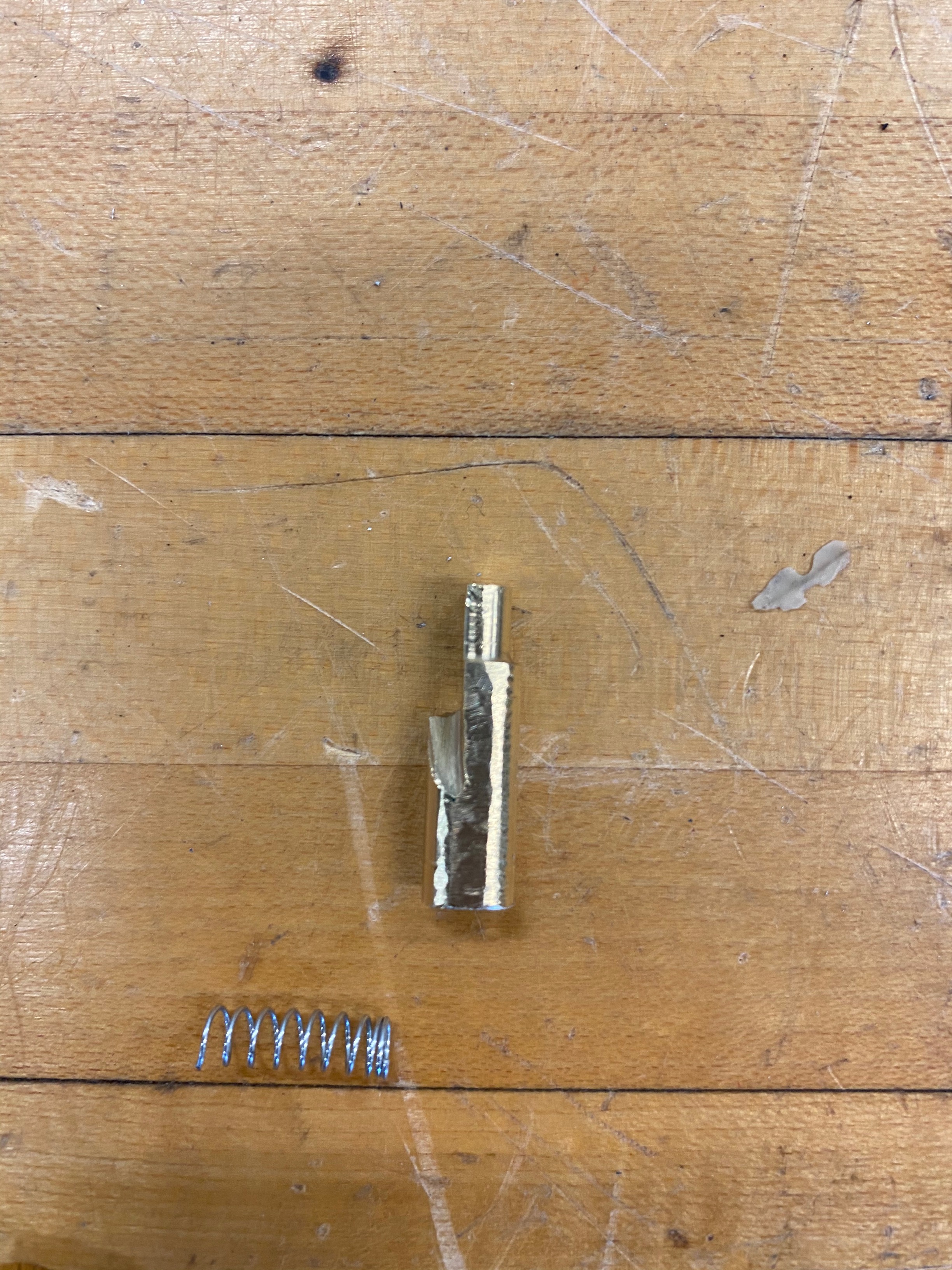
Image: Pin and compression spring.
Results:
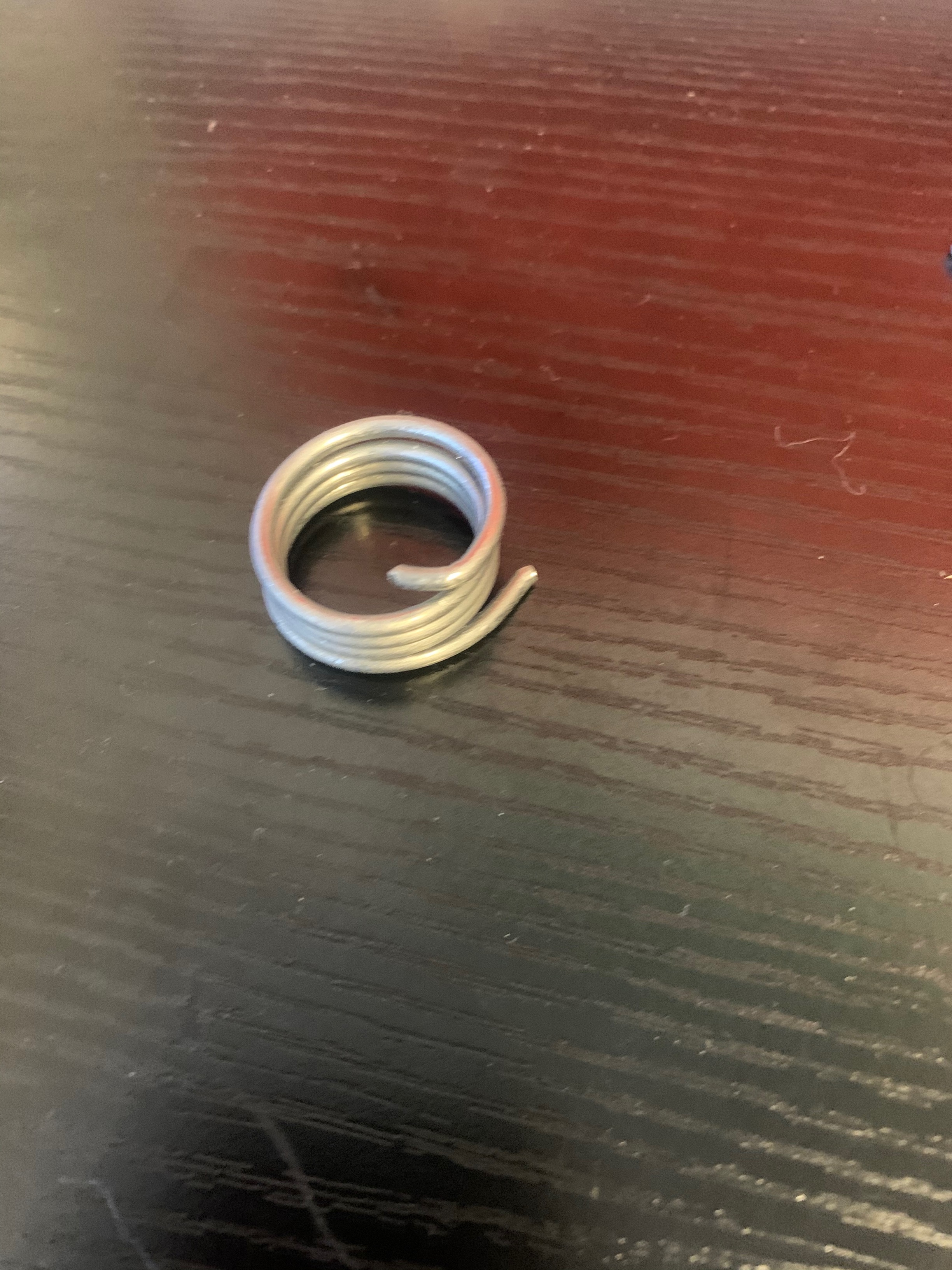
Image: Torsion spring.
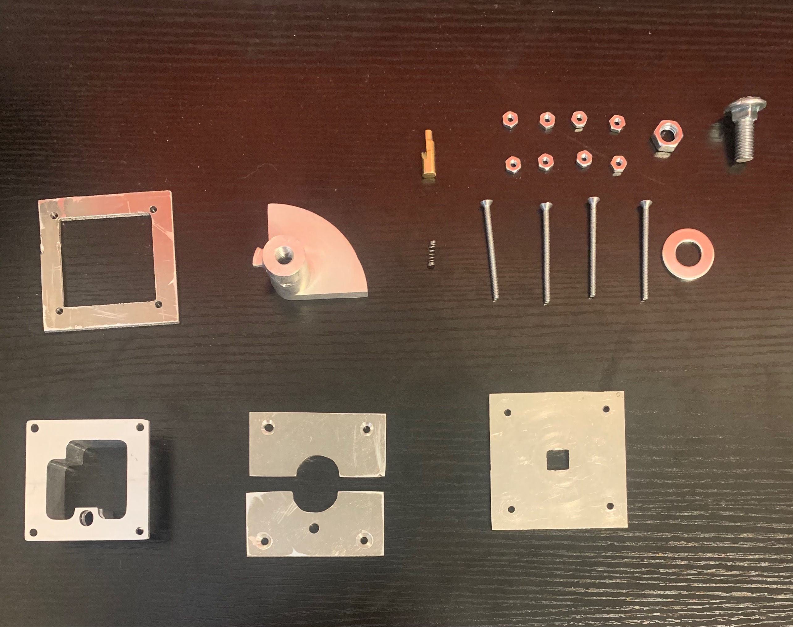
Image: All final manufactured assemble pieces.
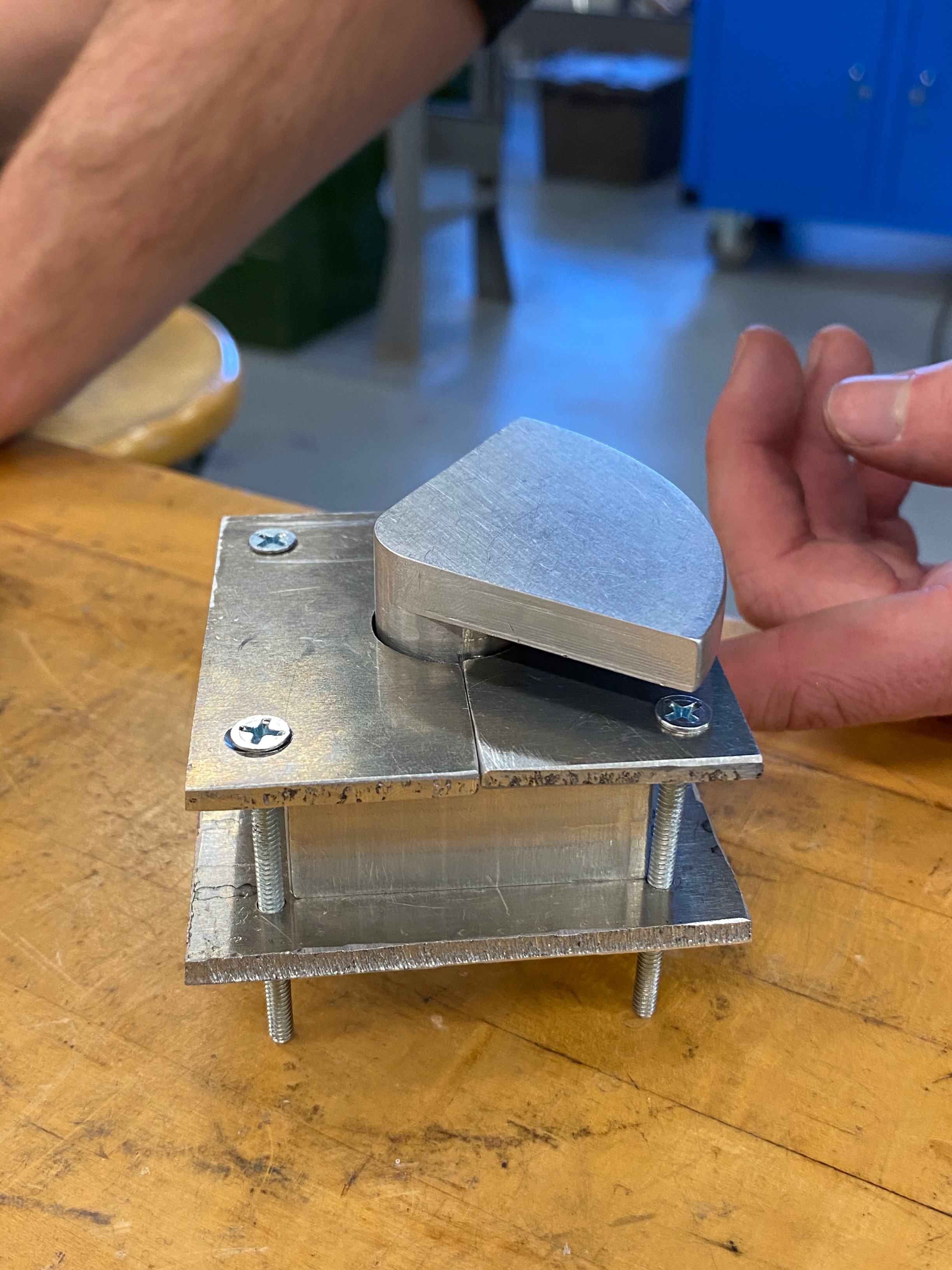
Image: Isometric view of system
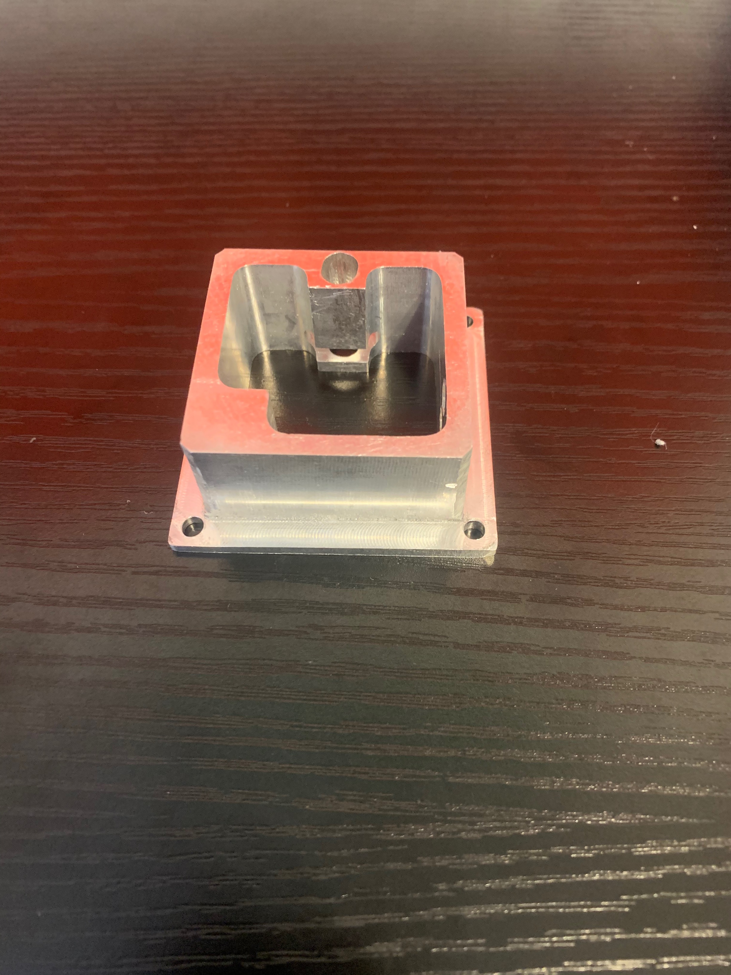
Image: Final manufactured housing(back)
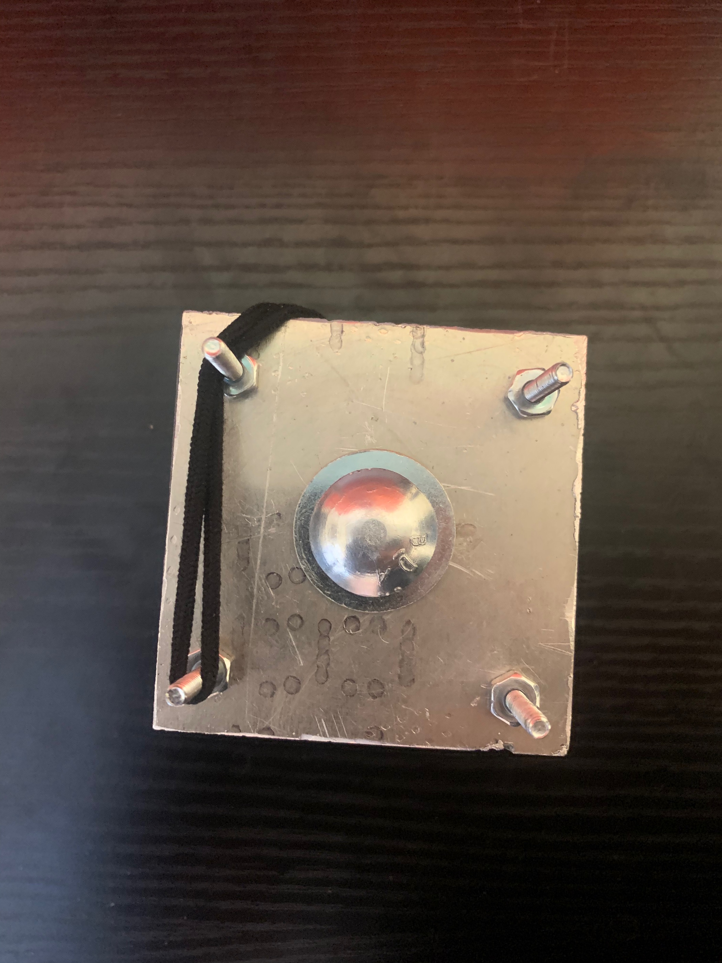
Image: Fully assembled system with hair tie.
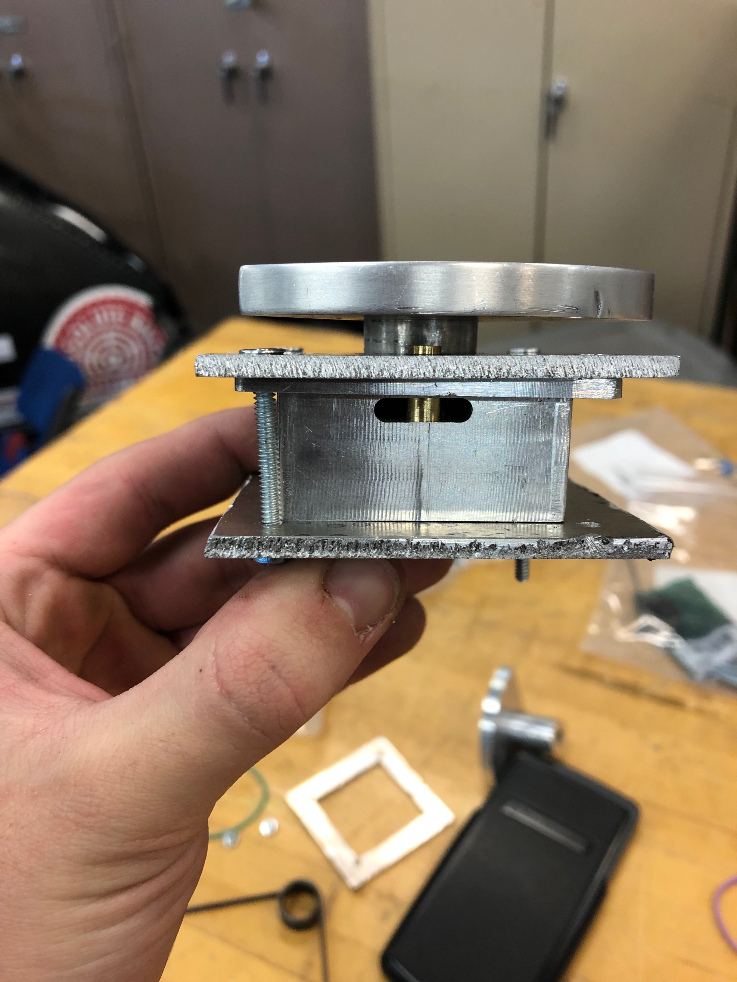
Image: Side view of assembled system.
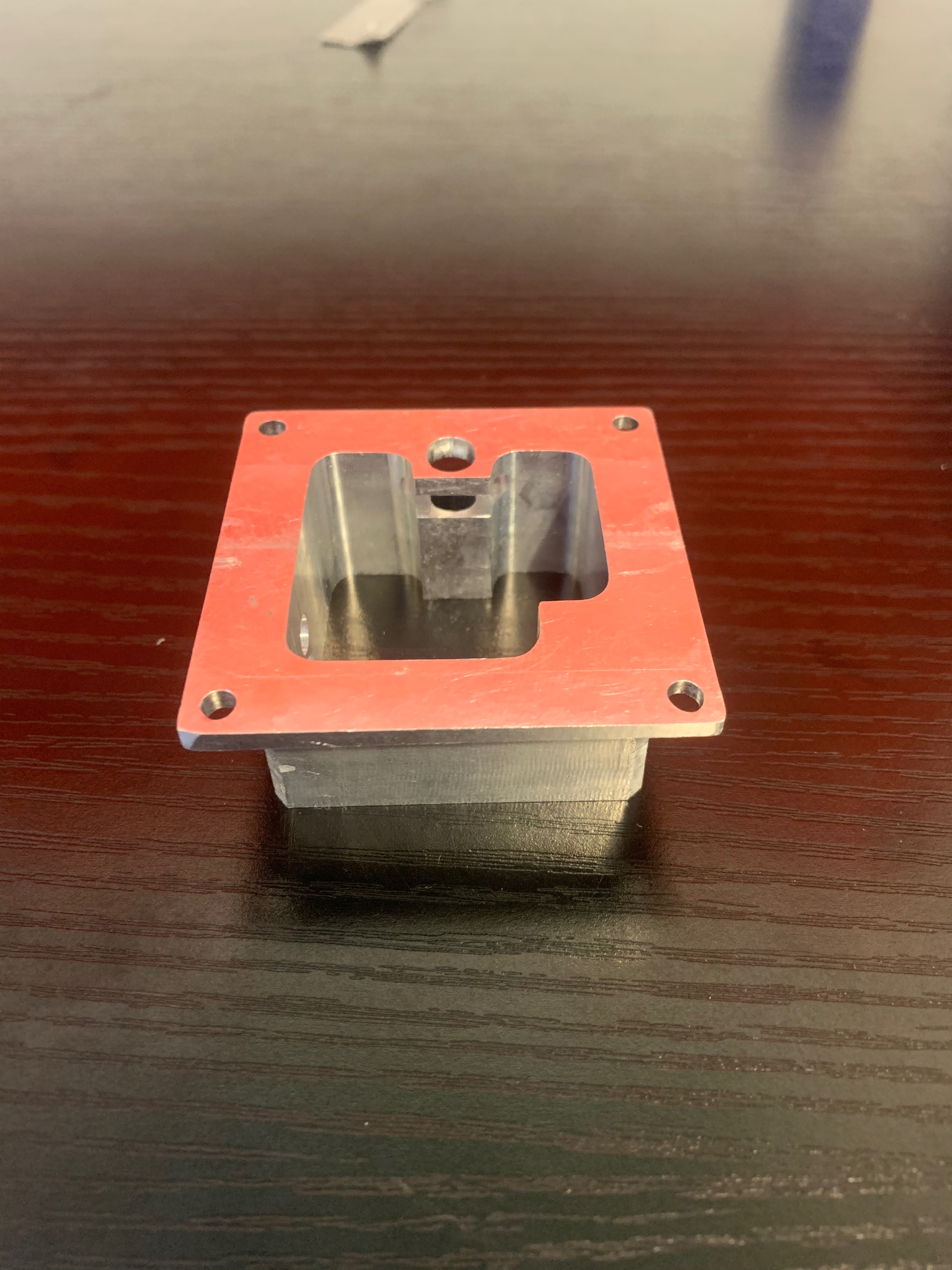
Image: Final manufactured housing(front)
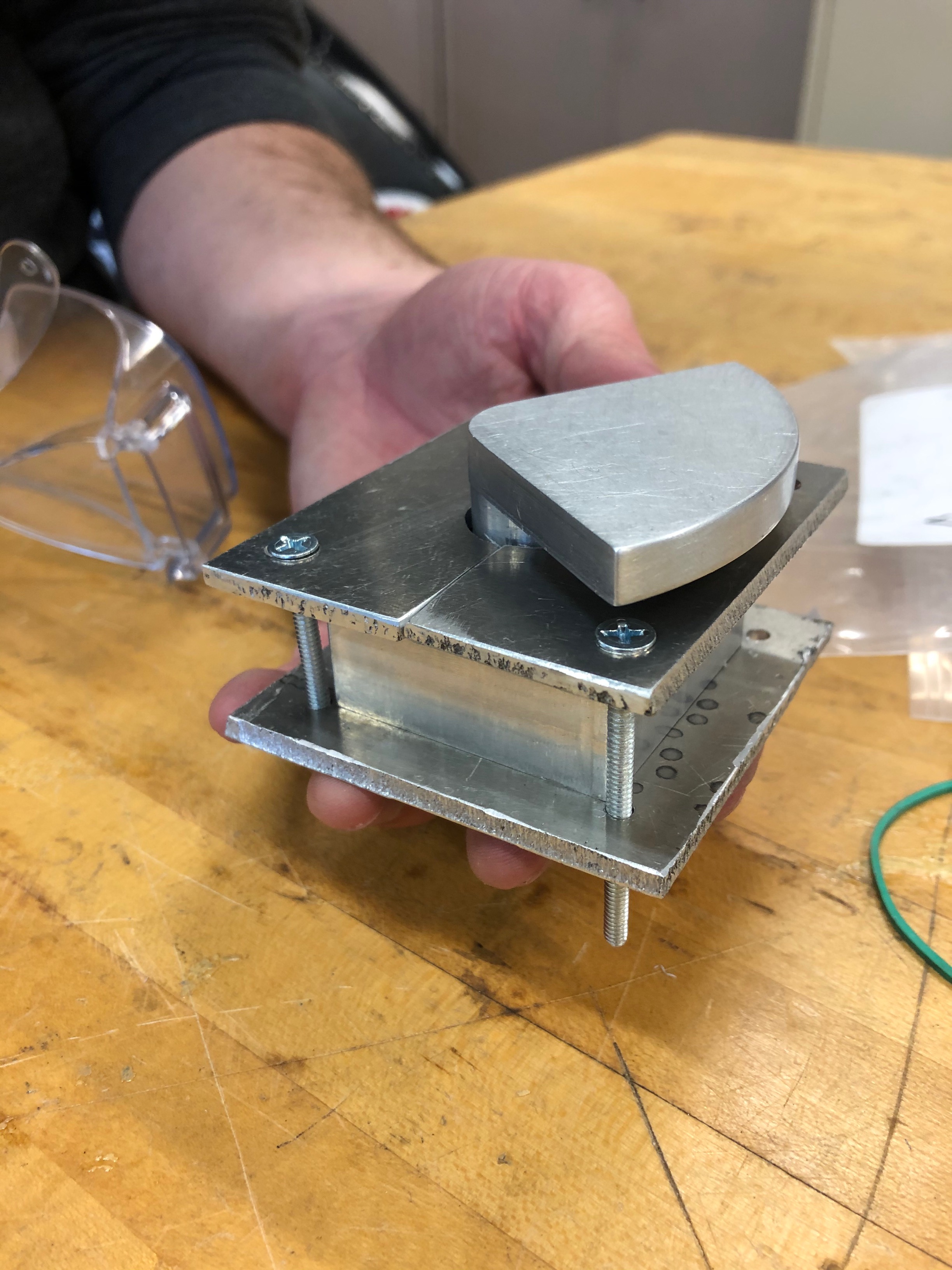
Image: Isometric view of system.
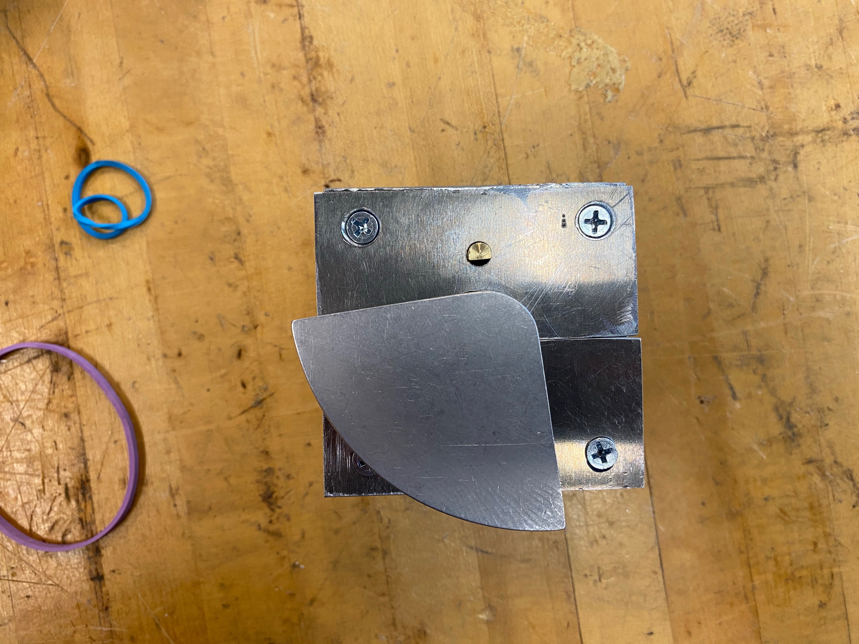
Image: Top view of assembled system.
Testing:
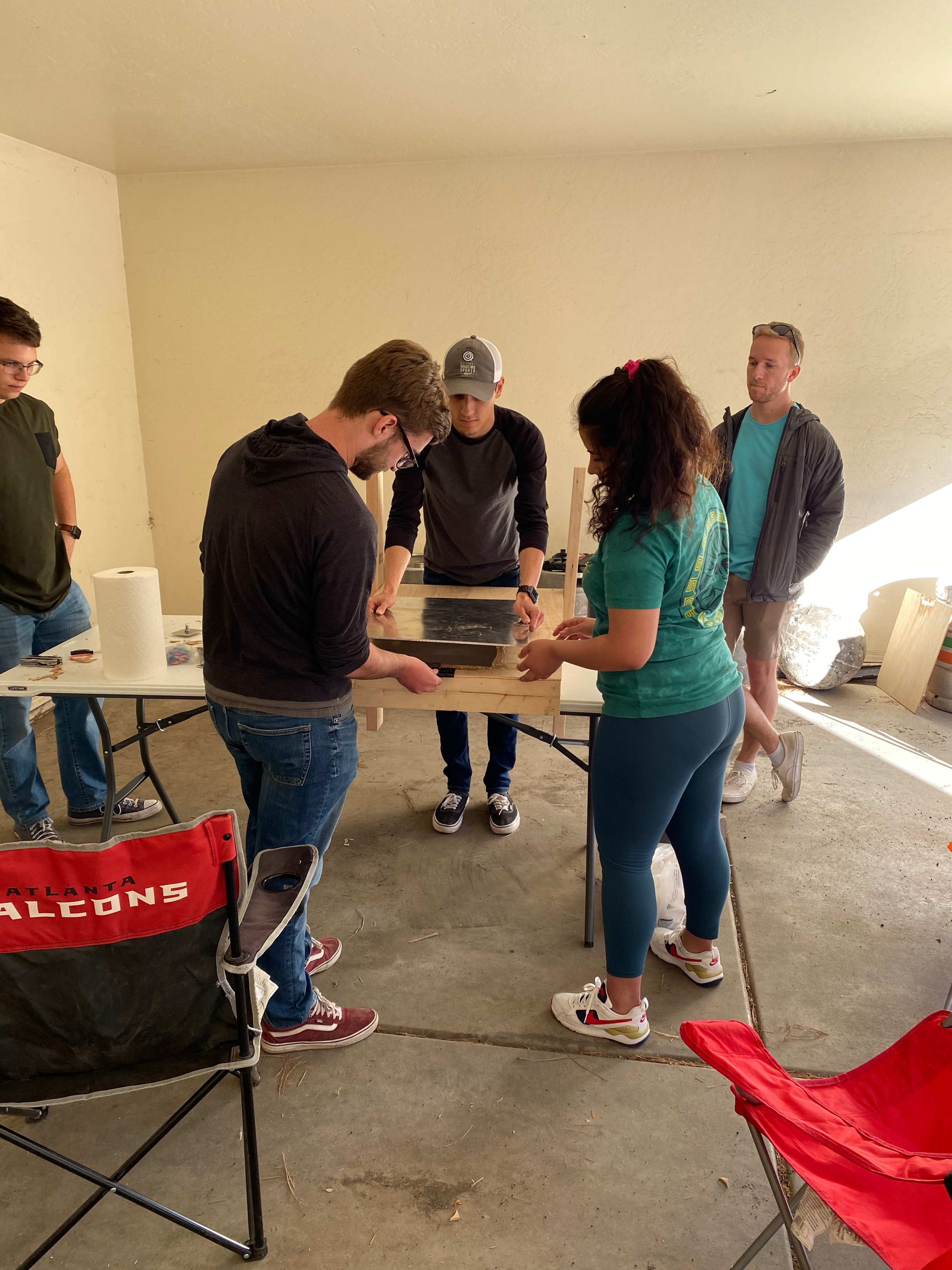
Image: Team meeting to build jig.
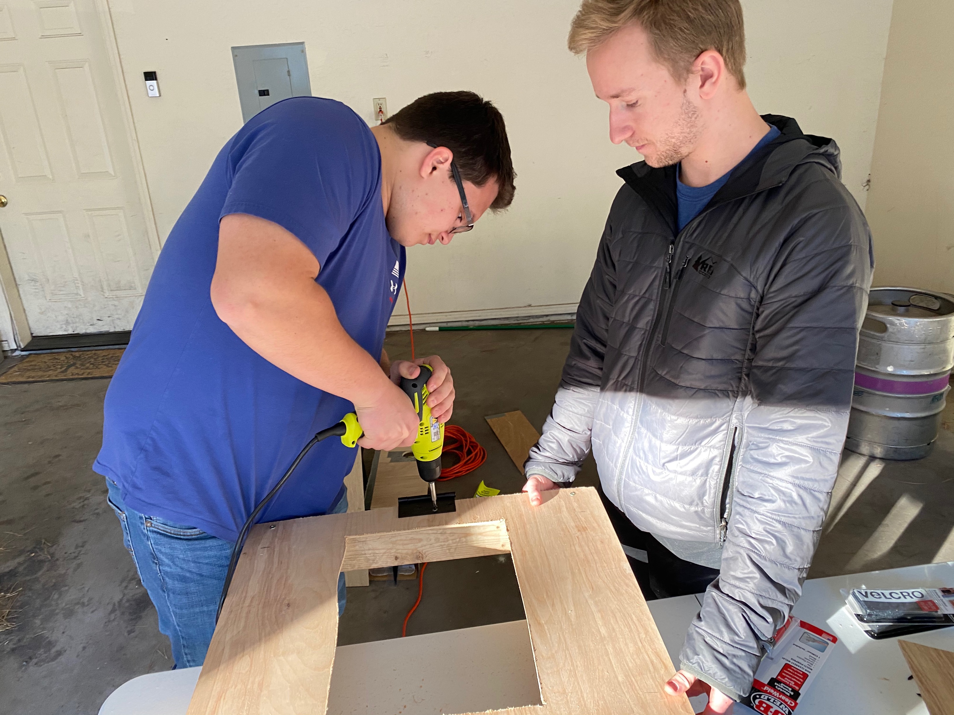
Image: Attaching hinge to jig frame.
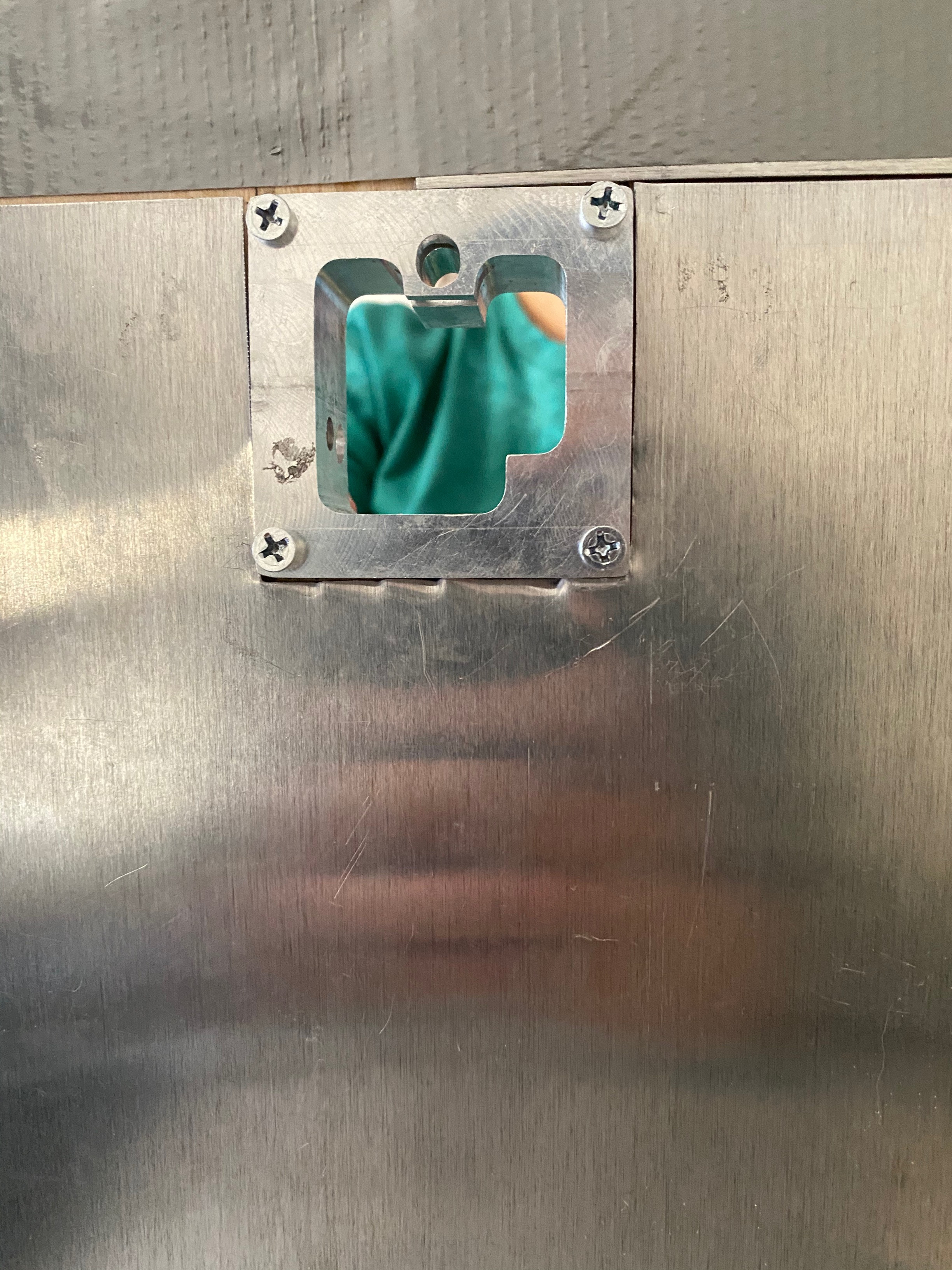
Image: Front view during installation process.
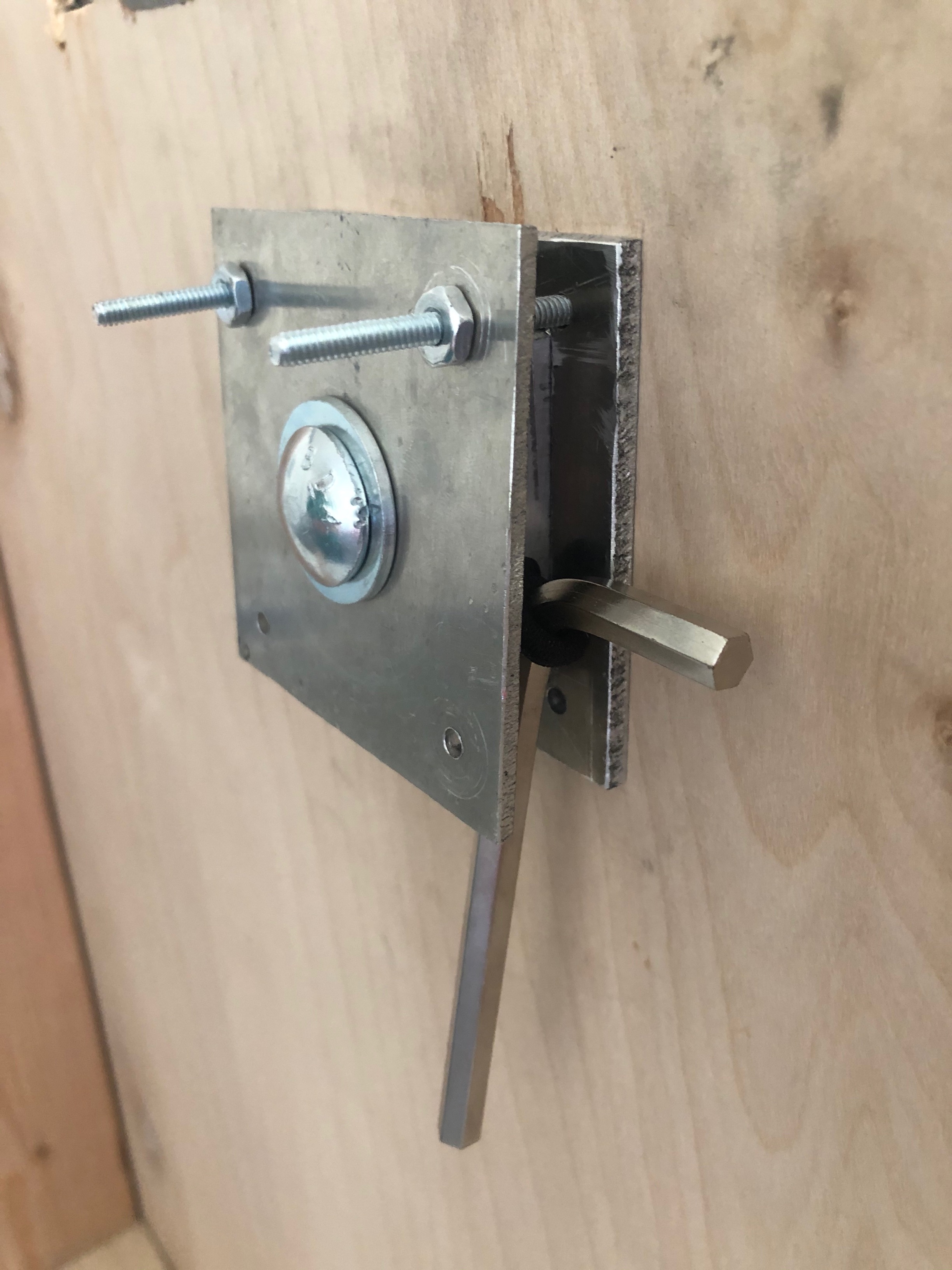
Image: Back view of installation process.
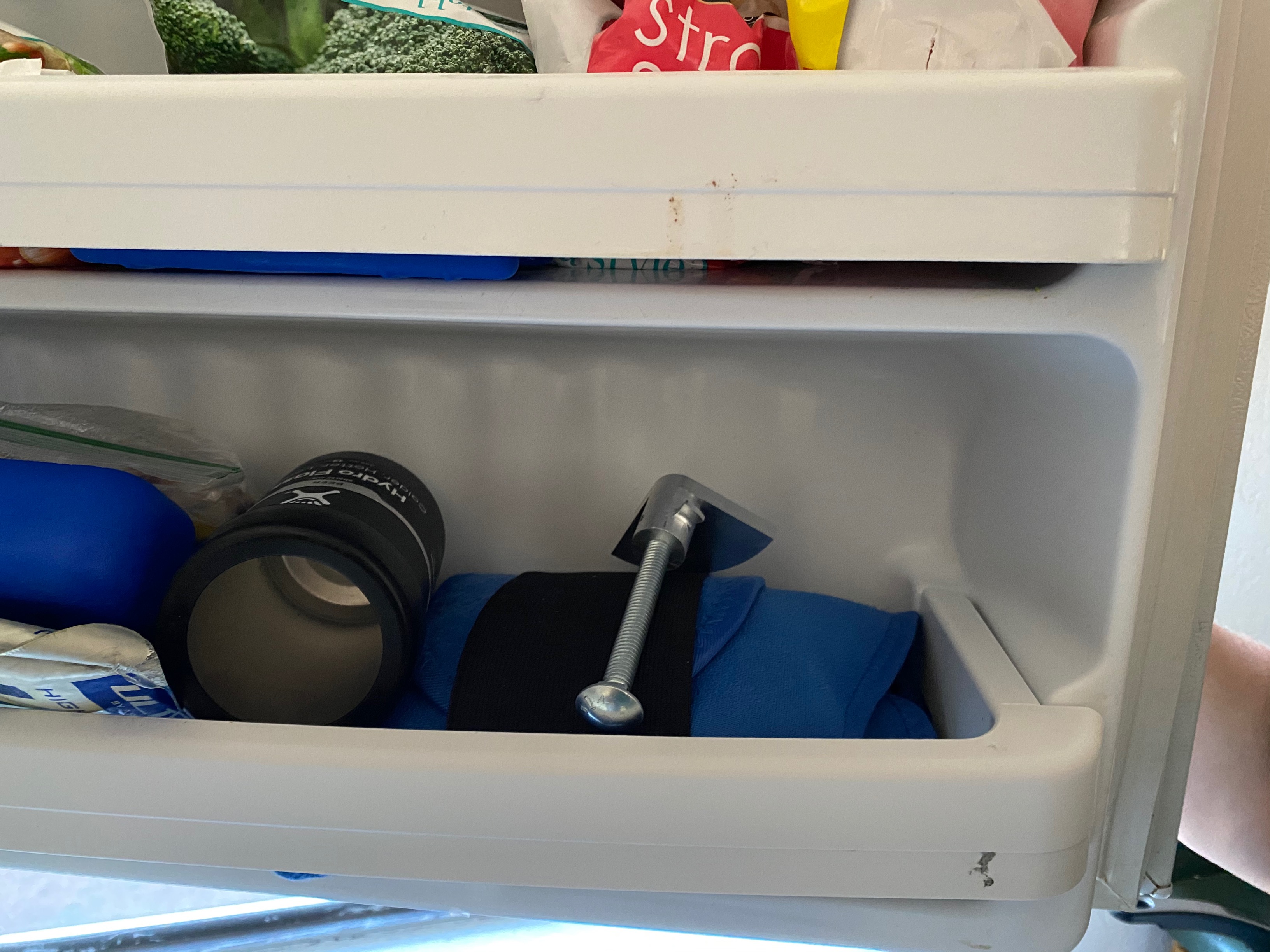
Image: Freezer testing.
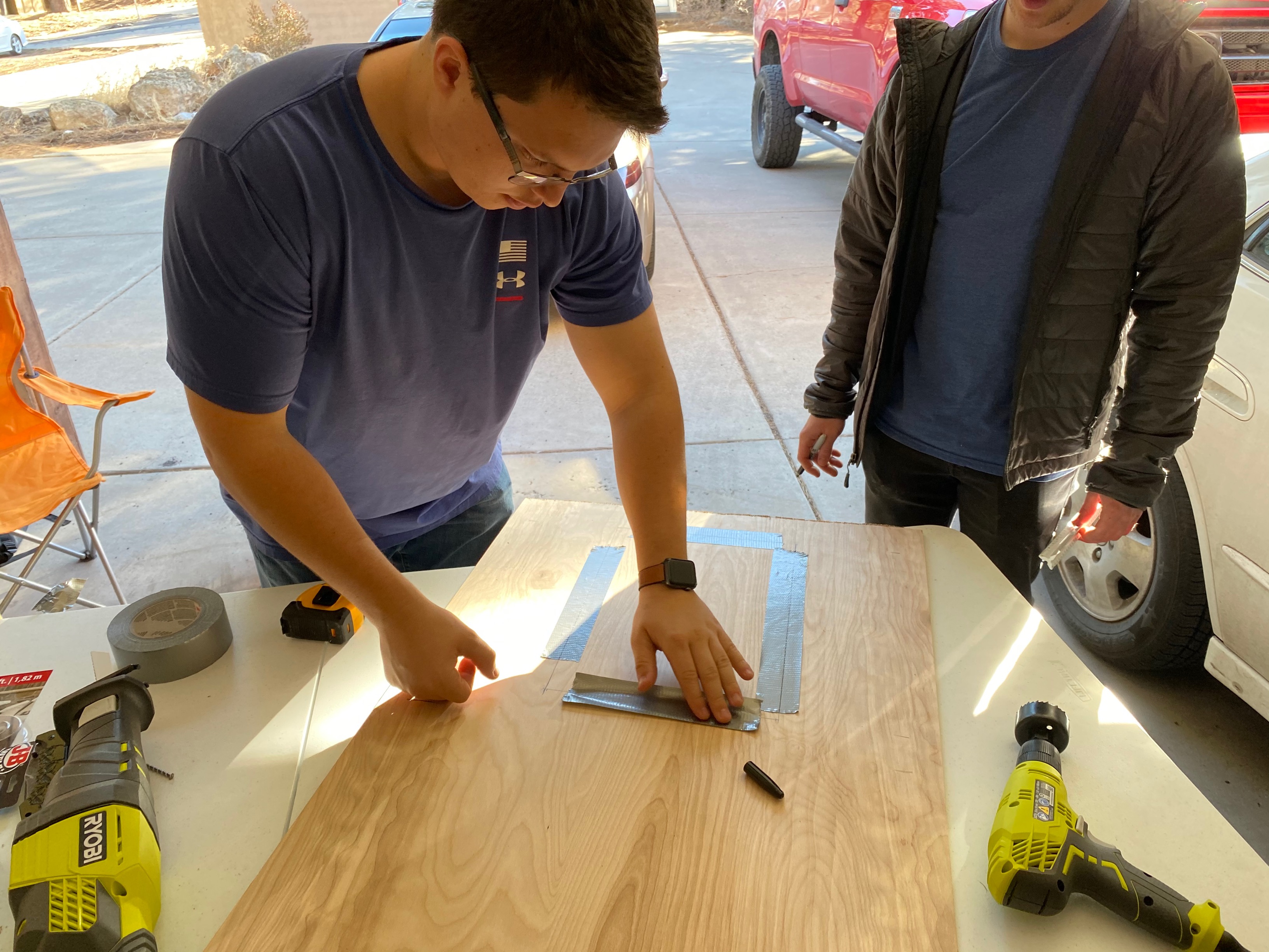
Image: Making the jig cuts.
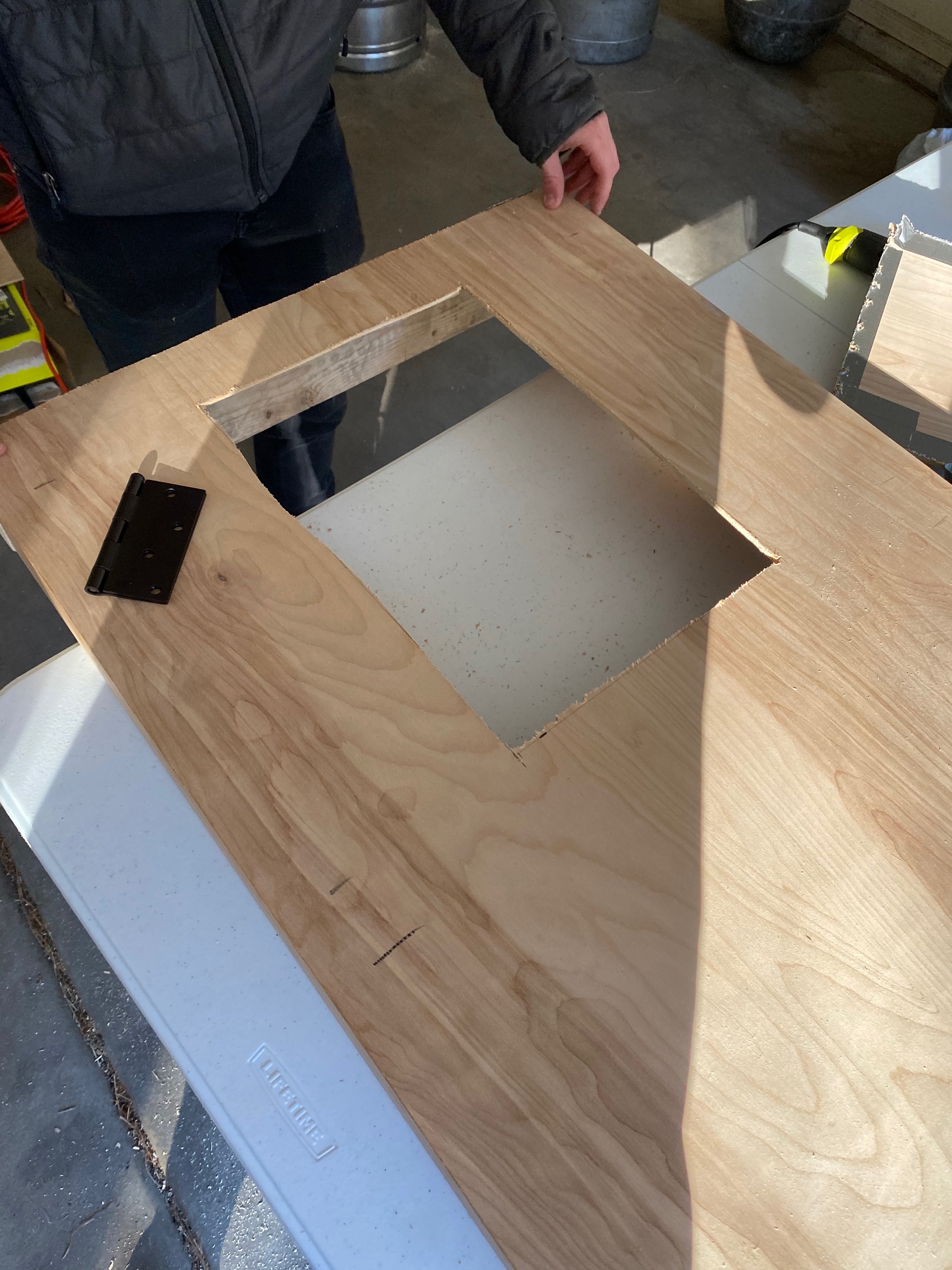
Image: Final jig front frame.
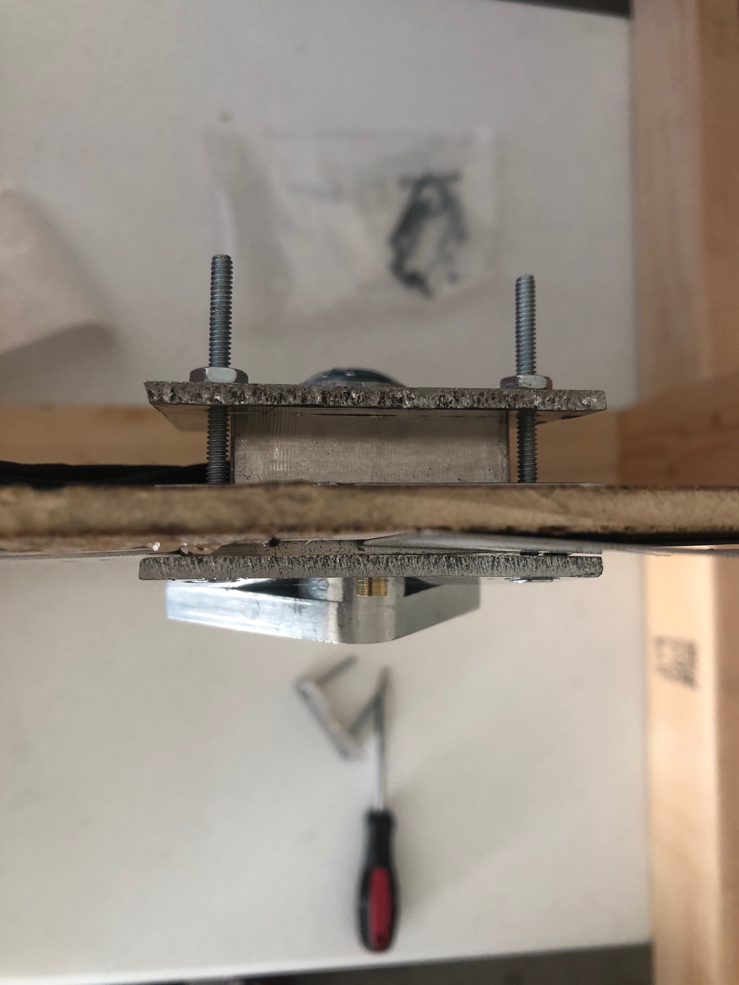
Image: Top view of functional testing installation.
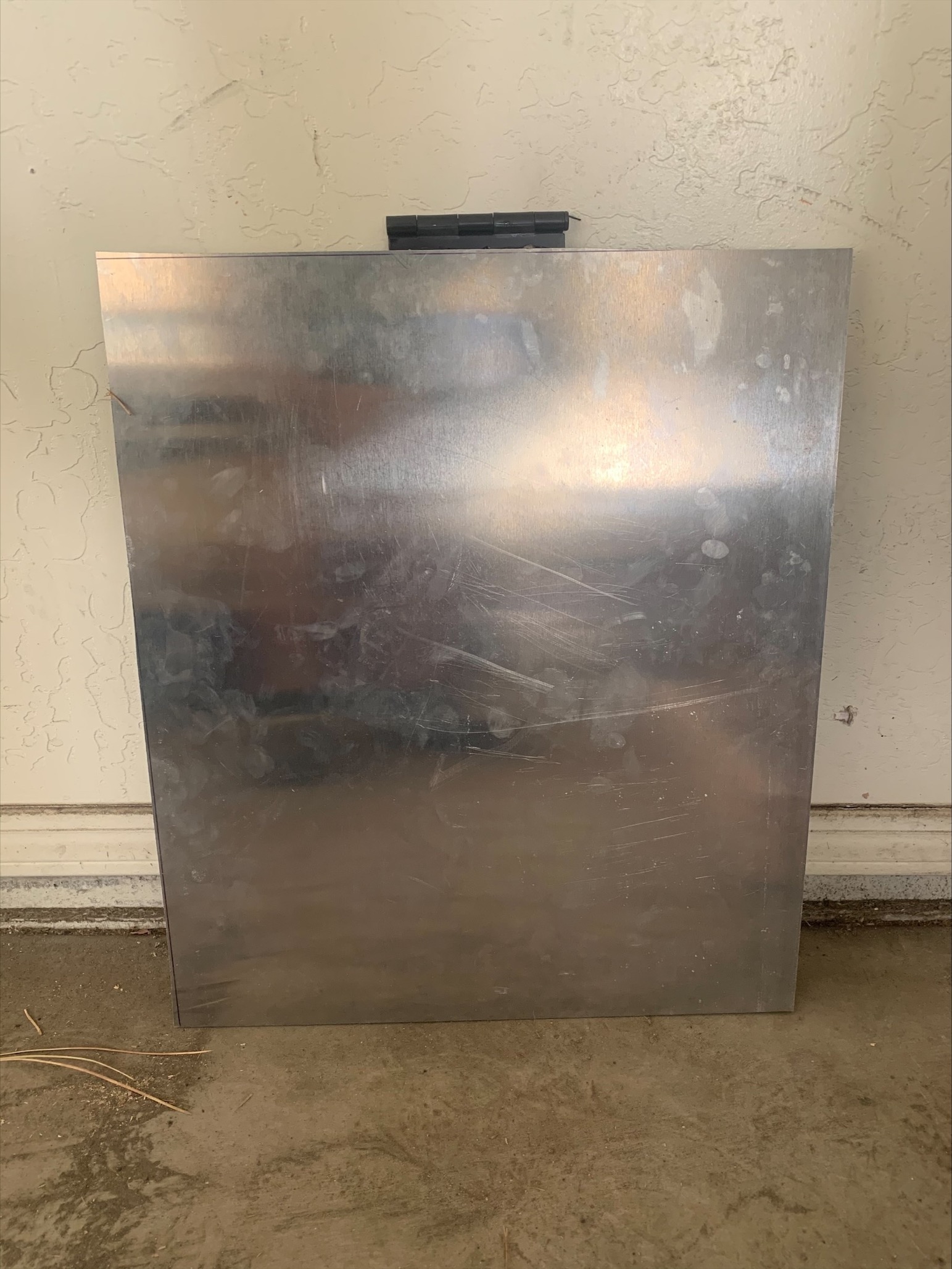
Image: Aluminium door.
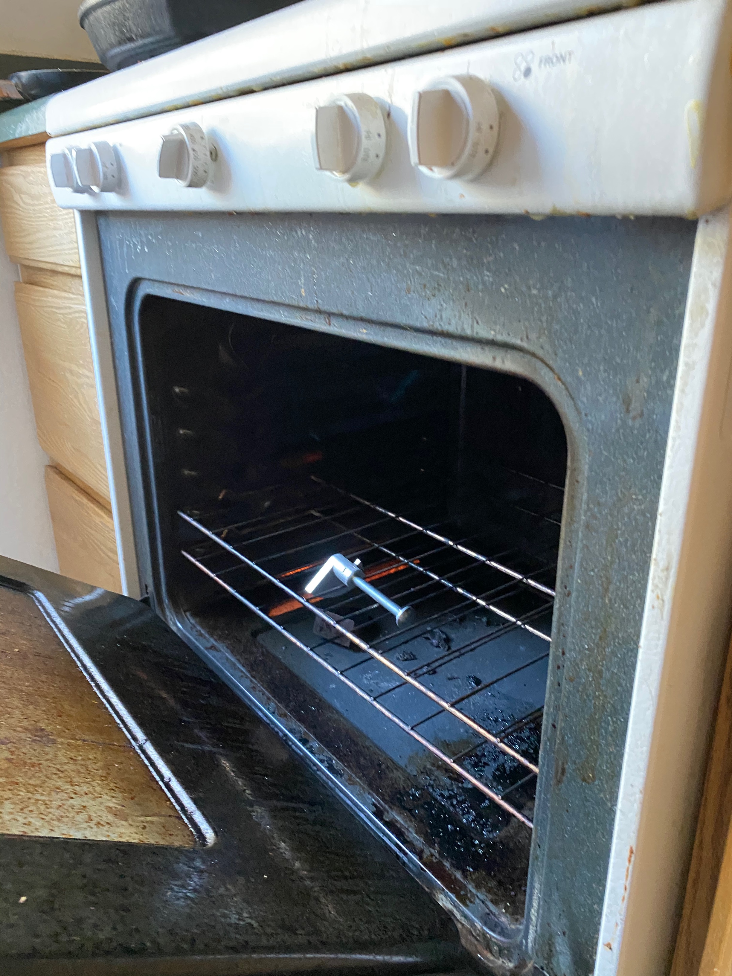
Image: Oven testing.
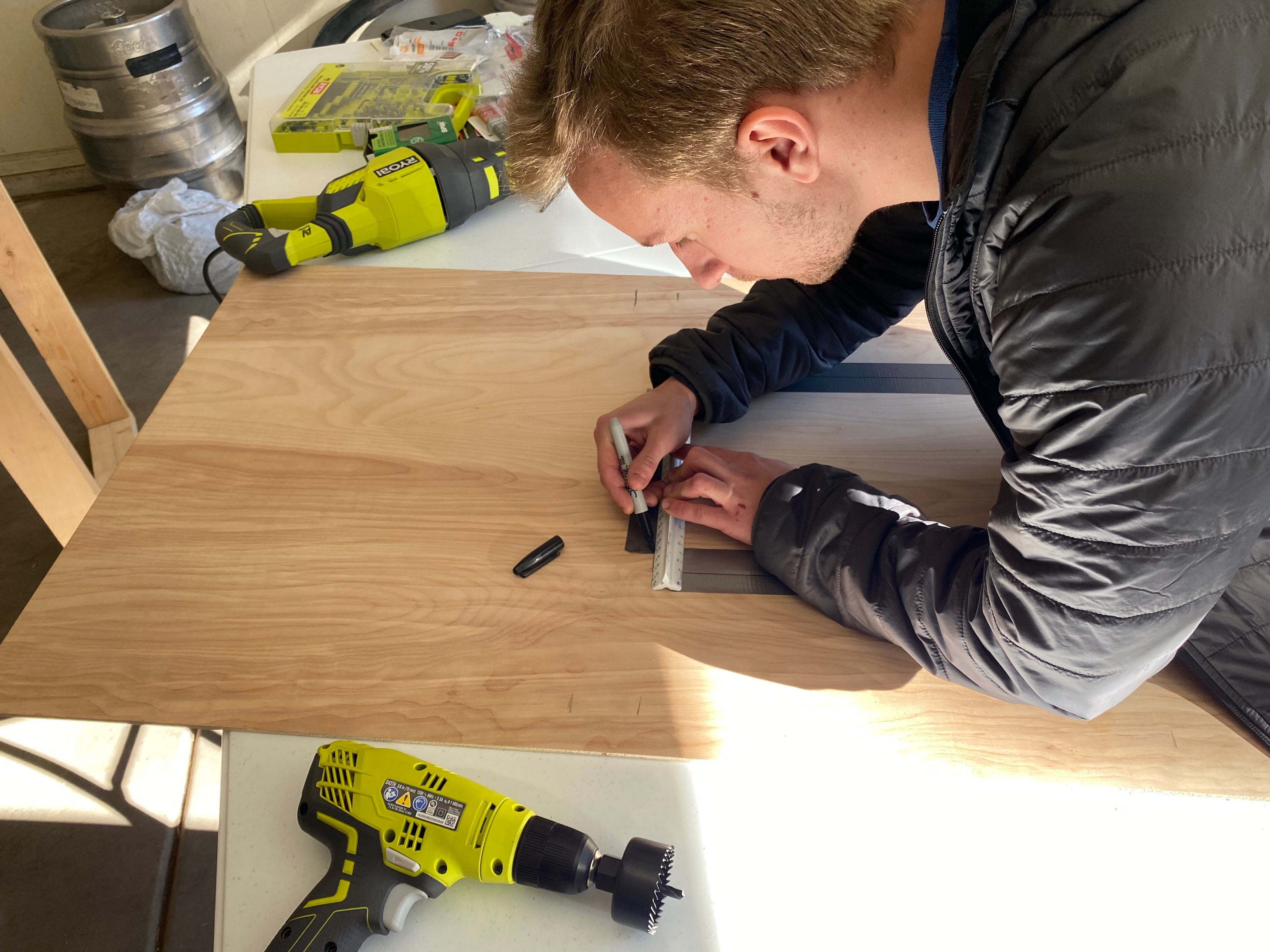
Image: Making the jig.
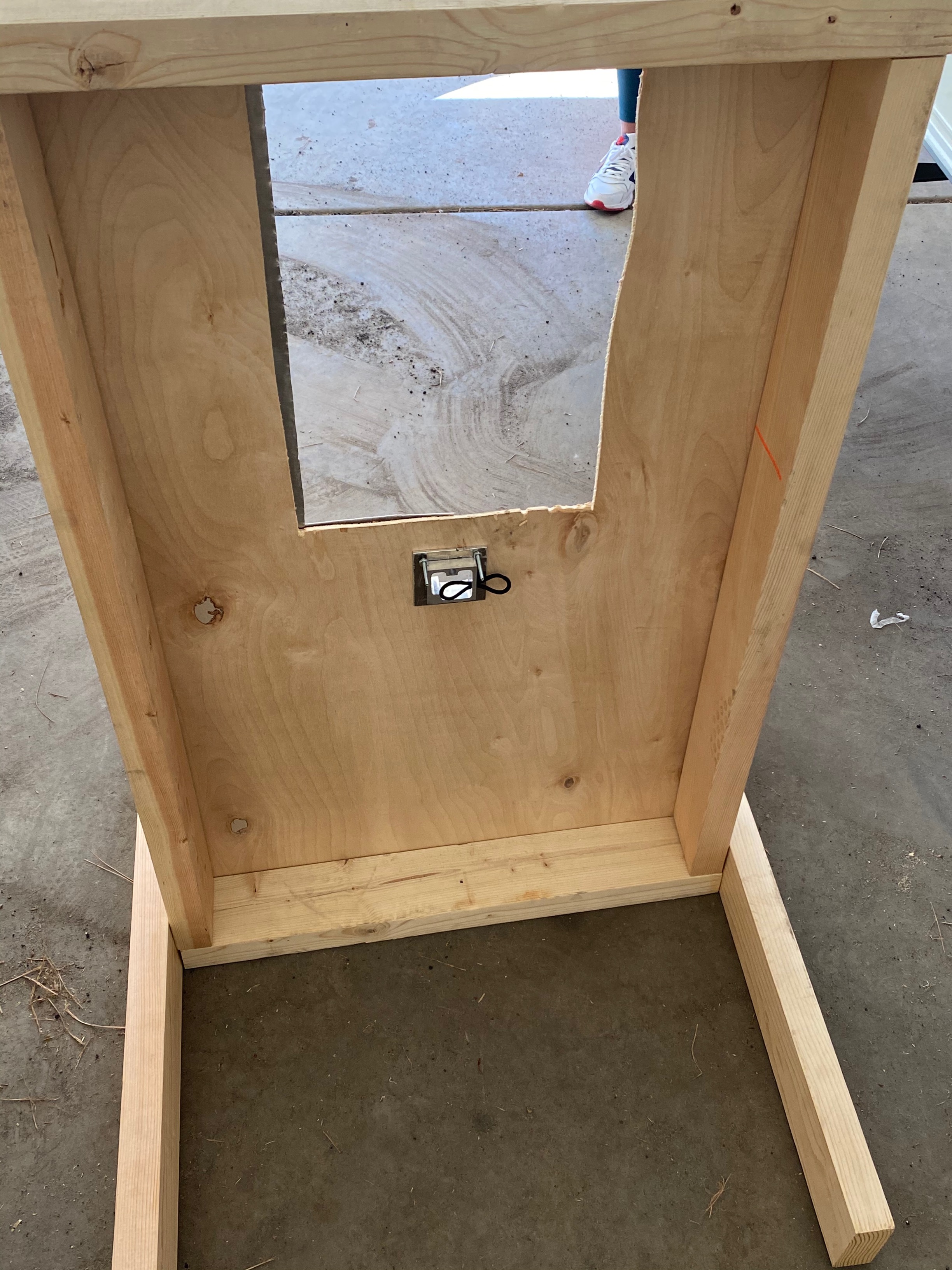
Image: Side view of assembly installed.
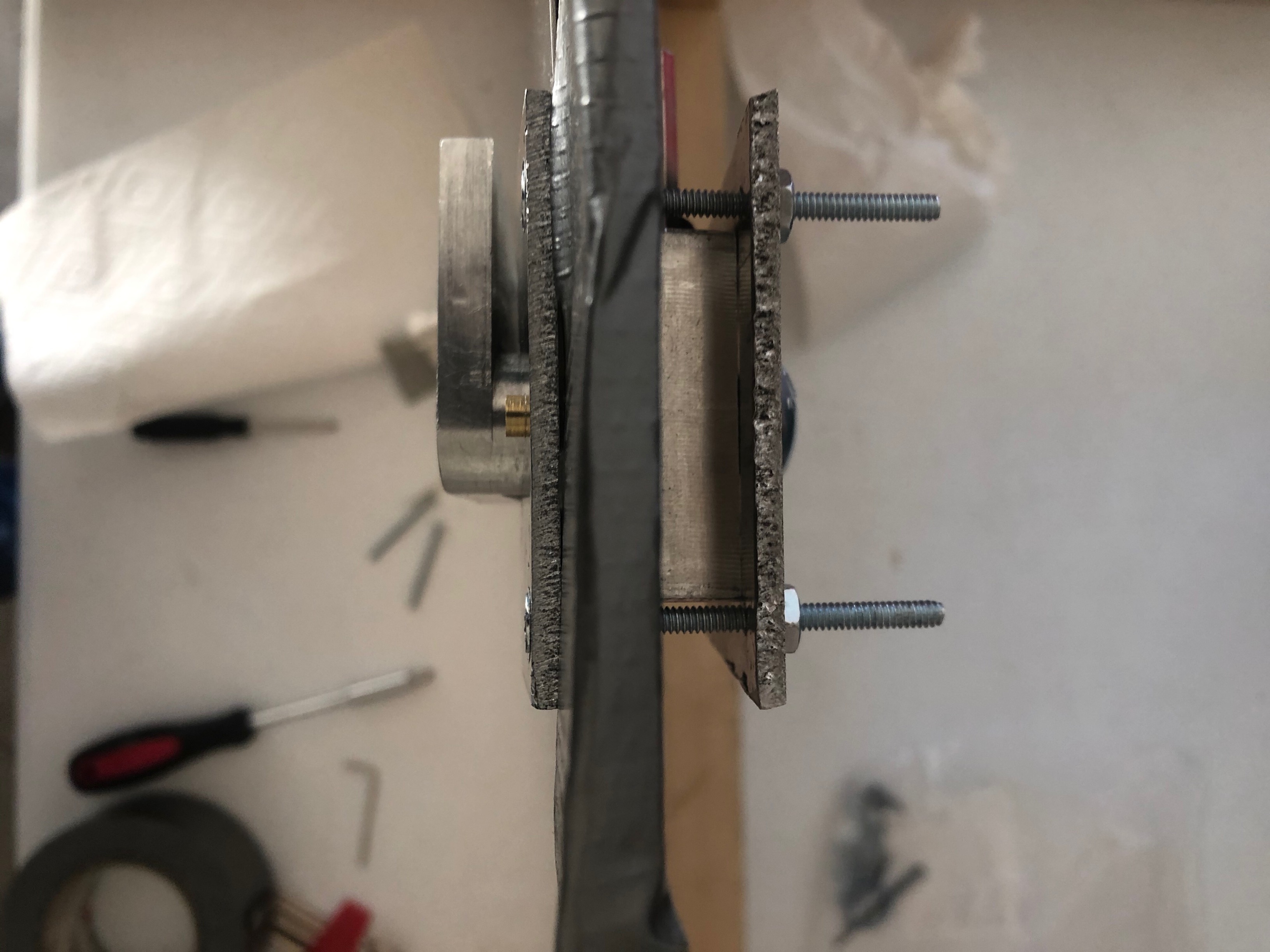
Image: Top view of fully assembly in the jig.
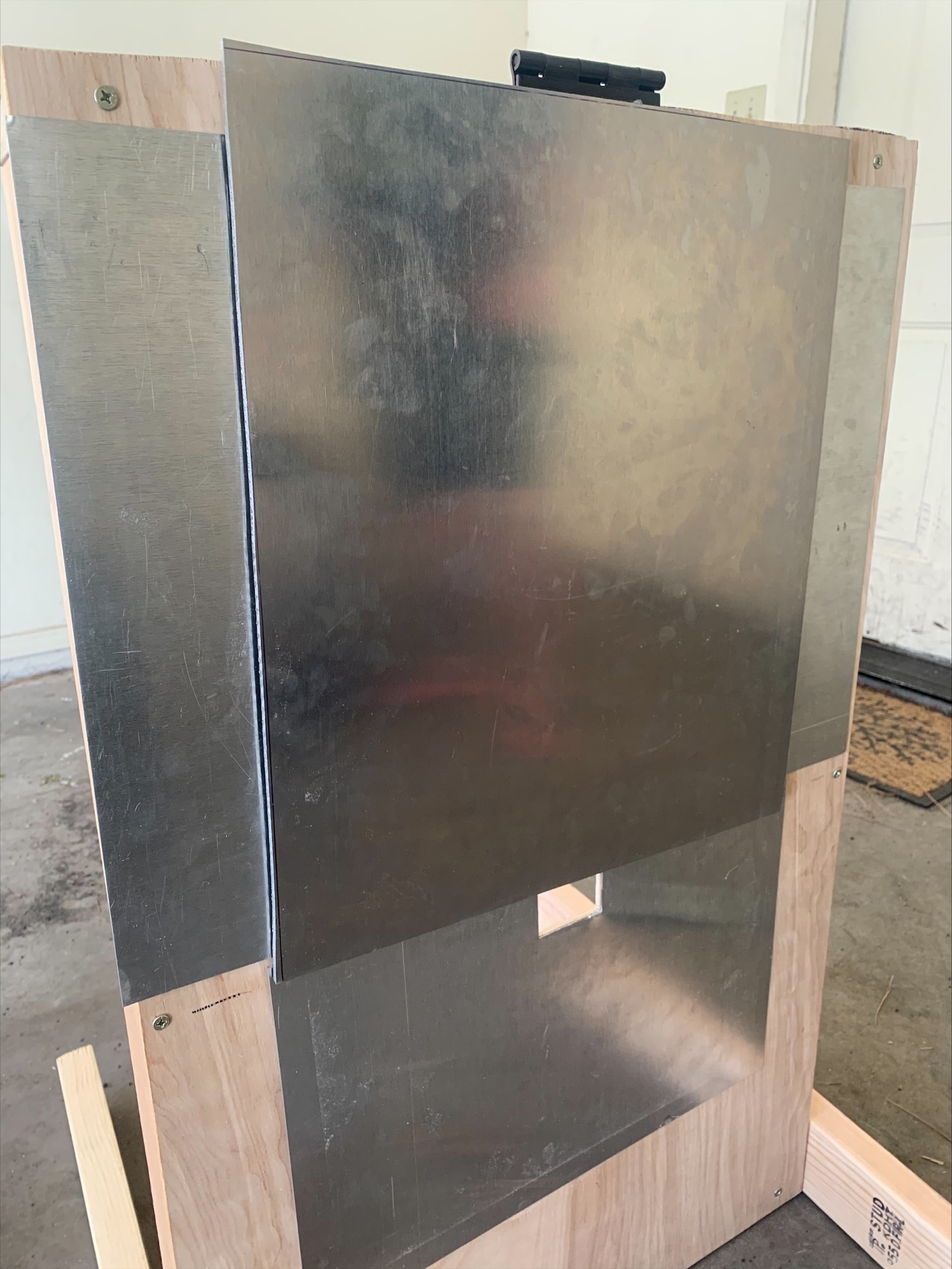
Image: Aluminium plated jig.
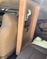
Image: Vibration testing, off roading option.
Bill of Materials:
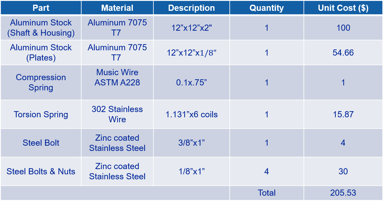
Image: Final BOM to create the product.
Budget:
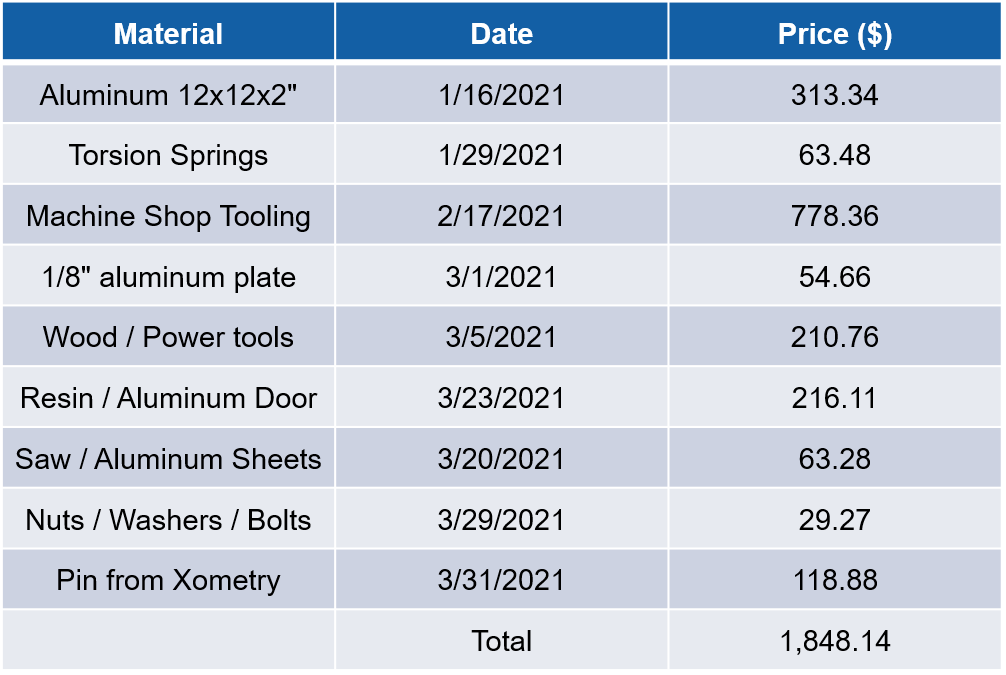
Image: Final summary of single product cost.