Project Description
This is the W. L. Gore & Associates sponsored Descending Thoracic Aortic Aneurysm Model project for Team A. Team A is a multi-disciplinary team consisting of both Mechanical Engineers and Electrical Engineers who are working under the guidance of engineering mentors to design, build, and test a replicable model of an aneurysm within the descending Thoracic Aorta. The main purpose of the aneurysm model is to have an anatomical testing apparatus in order to successfully deploy the Conformable GORE® TAG® Thoracic Endoprosthesis interventional device (Stent-Grafts) under simulated conditions, using non-biological materials. The aneurysm model is made of a transparent silicone material, so the deployment can be observed by the client. The procedure will be visible from the time the guide wire is inserted through the Femoral Artery to when the graft is deployed into the aneurysm site. Twelve aneurysm models were manufactured to prove the molding process is repeatable. The mold was designed in Solidworks and 3D printed. The anatomical model consists of different electrical components to maintain realistic conditions that occur within the human body. These simulated conditions include body temperature, blood flow rate, blood pressure, overall geometry, and life-like human tissue properties. An array of sensors are positioned within the system to provide real-time feedback and control of the components. With the aid of microprocessors, the data collected from the system is displayed on a touch screen display with a graphic user interface. Complete integration of the electronic components and mechanical parts will give the client the ability to administer realistic training exercises without the need for cadavers or live patients, and the model transparency allows for visual confirmation without the need of expensive imaging techniques.
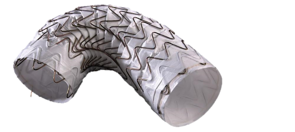
Conformable GORE® TAG® Thoracic Endoprosthesis:
Project Constraints
Through an extensive literature review and collaboration with W.L. Gore & Associates, the engineering requirements shown in the tables below were created. The requirements are split up into two categories: quantitative and qualitative engineering requirements. While the quantitative requirements are met by staying within a defined tolerance, the qualitative requirements are met through observation or a simple pass/fail criteria. Creep, durometer and compliance were characterized to observe their effects on the system. Testing procedures were created for each quantitative requirement. These procedures justified and determined if each criteria passed or failed. These testing procedures can be found in the final report.
Decision Matrices
For each subsystem of the design, a Pugh chart was created to weigh various options against each other.
Pump

Aneurysm

Heater

Flow Rate Sensor

Pressure Sensor

Temperature Sensor

Final Design
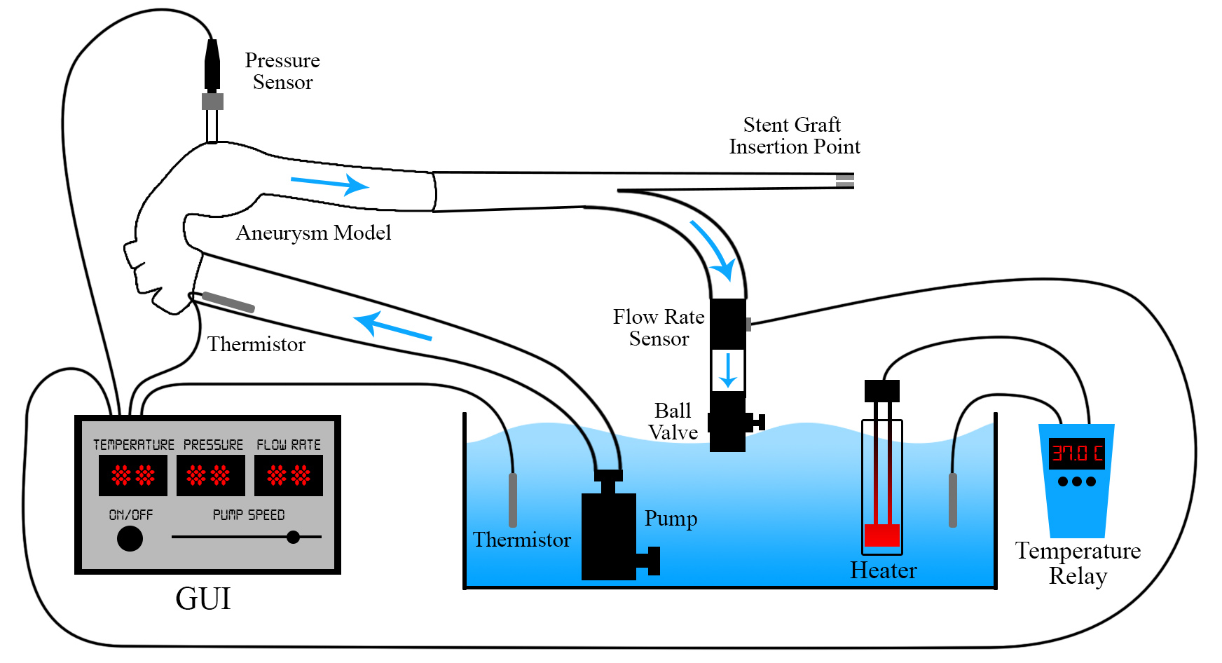
The final design consists of the following components:
- Steady flow pump
- Silicone molded aneurysm
- Water reservoir with aquarium style heater
- Turbine flow meter
- Single pressure sensor
- Thermistor
- Touch screen GUI
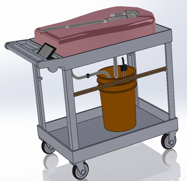
- Mobile cart design
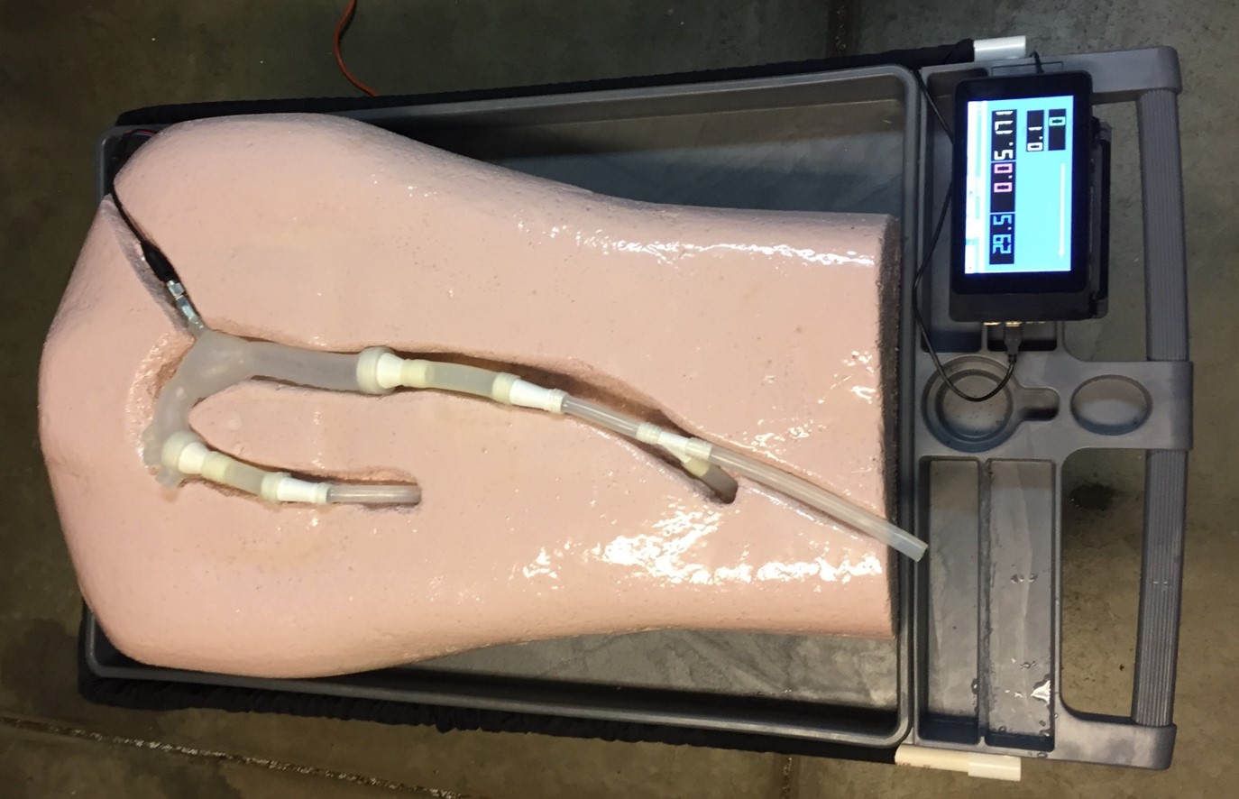
- Upper body foam display
The layout of these components can be seen in the figures below.
Manufacturing Process
One of W.L. Gore & Associates’ requirements was to document and provide steps for the manufacturing process, so that it could be replicated if their team needed to create more aneurysm models.
Step 1: Assemble Mold
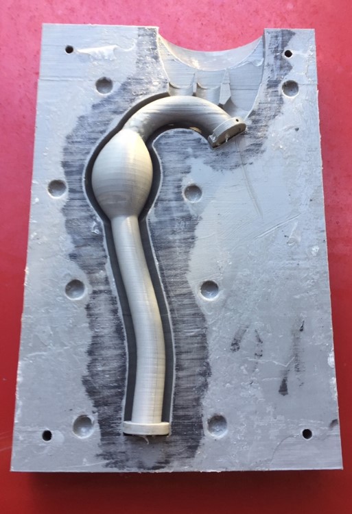
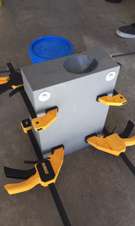
The first step in molding the aneurysm model is to lubricate the core and outer shells. Attach the locating rings onto the ends of the core, and insert into the outer shell, as seen in the first picture below. Then secure the two halves of the mold with bolts and clamps, which can be seen in the second picture below.
Step 2: Prepare Silicone
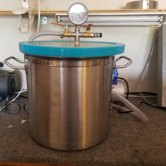
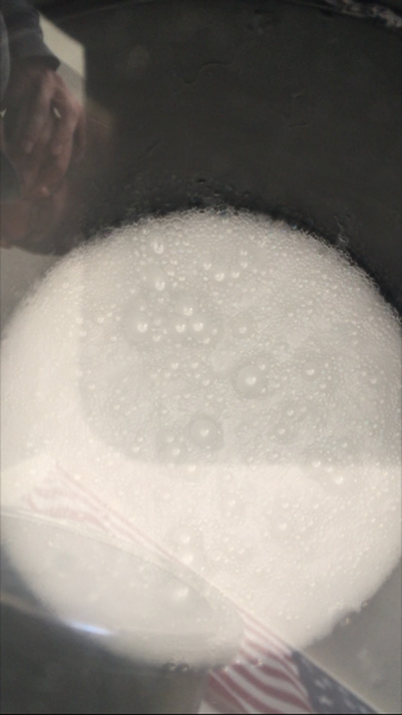
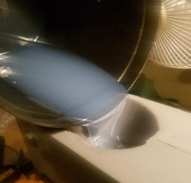
The second step is to prepare the silicone. After mixing the 2-part silicone, it is placed in a vacuum chamber to expel any air within the mixture. The picture below shows the silicone mixture inside of a vacuum chamber. The trapped air moves to the top until all of the air has left the mixture, at which point the bubbles collapse in a rapid manner. Once the bubbles have collapsed, the mixture is ready to pour into the mold.
Step 3: Pour and Cure
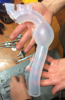
Once the silicone has been poured into the mold it is left to set for at least 12 hours. When the aneurysm model is ready to be removed, the mold is taken apart and the inner core is pulled out of the model. The silicone has a very high elasticity, so pulling the core out is not an issue as long as it is properly lubricated.
Design Iterations
Two iterations of the aneurysm model were created before the final model was formed. These iterations are described below.
Iteration 1
The first prototype was created by applying pressure to an acrylic tube that was heated with a blow torch. This model did not work for the purposes of the project, so it was thrown out.
Iteration 2
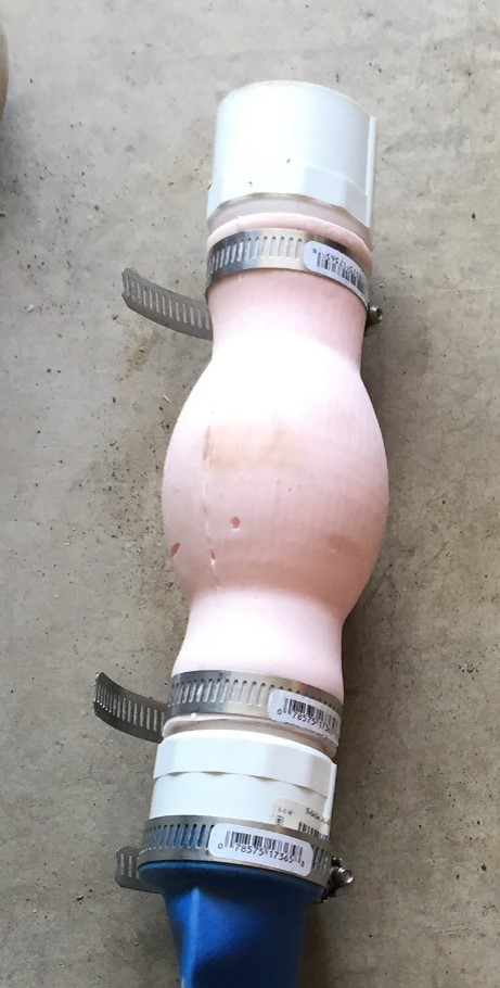
The second iteration was molded out of urethane rubber in a 3D-printed mold. This iteration was a proof of concept of the molding process, and did not represent the final anatomical dimensions. Air pockets in the model were formed when pouring the silicone into the mold, so a vacuum chamber was purchased for the next iteration.
Final Aneurysm Model Design
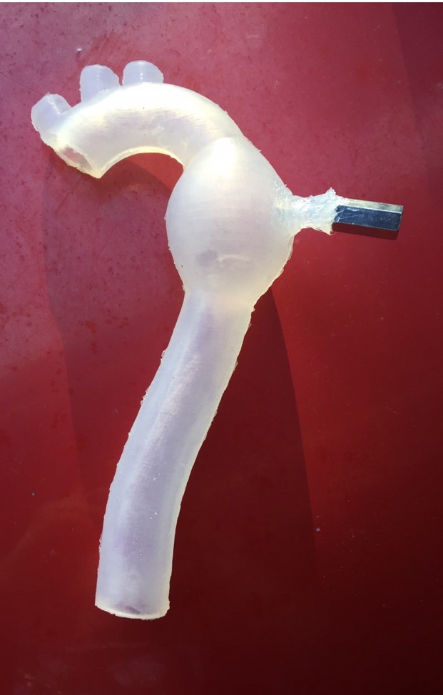
The next iteration included the final anatomical dimensions, a connection point for the pressure sensor, and was made out of a transparent silicone material.
This was the final model used in the system, but the mold’s core had to be modified after the original core snapped. The final core was 3D printed as a solid piece as opposed to a hollow shell.
Conclusions
The team successfully built and tested a replicable model of an aneurysm in the descending thoracic aorta. All qualitative and quantitative requirements were fulfilled, and the testing procedures proved this. The Conformable GORE® TAG® Thoracic Endoprosthesis was deployed in the aneurysm model under anatomical flow, pressure and temperature conditions. Based on the aneurysm model geometry when the system is running, a 31 x 20 Comfortable Gore® Tag® device should be used for deployment in this model. Even though the device that W.L. Gore deployed was shorter than what was required, the device still deployed correctly, and the models transparency allowed for the user to visualize the stent graft’s deployment. The aneurysm model manufacturing process was documented, and all resources necessary to replicate the aneurysm model have been provided in the full report.
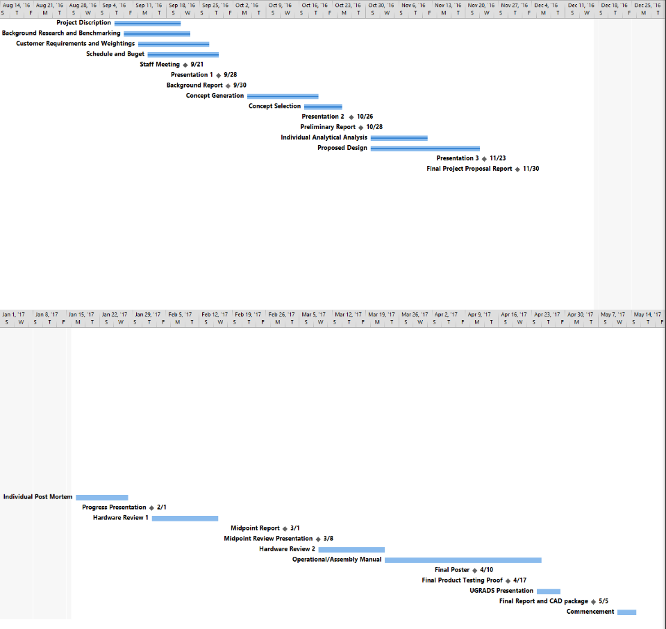
Gantt Chart & Bill Of Materials
Project Location
Engineering Building, 2112 S Huffer Ln, Flagstaff, AZ 86011
CAD Drawings Archive
