Project Development
The first thing our group did is researched existing chassis and suspension types to determine the best choice for our vehicle. We designed several concepts for the frame, front and rear suspension. After a group decision and advising we chose to use a truss style frame, A-arm style front suspension, and trailing arm linkage rear suspension all using 6061-T6 aluminum tubing.
We purchased aluminum tubing and began building during December. Using a horizontal band saw we cut the tubing into appropriate lengths. If tubing was needed for an angled joint we used a hole saw to notch the tubing to fit as our design called for. We then used a TIG welding machine to weld the frame, and suspension parts. The frame and suspension components which were aluminum were then heat treated to counteract the strength loss after welding.
The suspension was installed on the frame by March with our donated hardware and the bushings which we custom made in the shop. At this time we also installed our discounted FOX Float RL Air shocks.
After this the major integration with the other four sub-teams began and was finished shortly before our competition in Texas on March 30th. This did not allow for any road testing time, so we did not know how well our systems would work. The car was unfortunately unable to complete the competition due to catastrophic electrical failure of the motor controller. With these issues in mind we have brought the car back from the competition and fixed the critical issues.
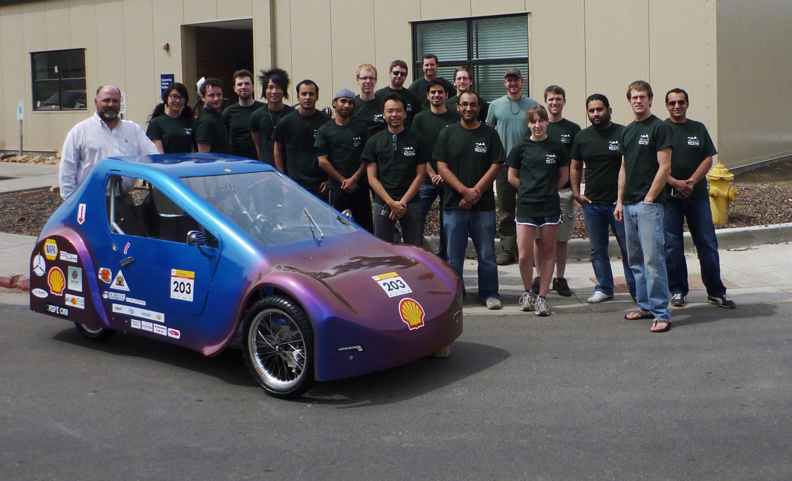
We now have a fully functional and efficiently running car!
Final Products and Features
Chassis

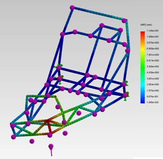
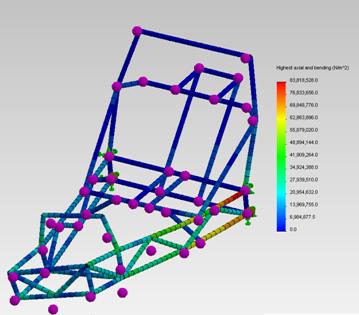
This is the completed chassis and suspension system. Displacement and stress analysis were done on the frame using SolidWorks, This data is shown in the two below pictures. With a 500 N force, likely the maximum this frame will see, applied the frame displaces minimally. With the same force, and the rear of the frame locked into place, the stress is maximum at the rear, but not a critical or damaging stress. This analysis showed the group that the frame could tolerate a large force if the worst case scenario happened.
Front Suspension

The above picture is the completed A-arm front suspension with attached wheel and steering components. This suspension holds the vehicle at the required ground clearance and prevents the car from receiving damage in the event the car hits a large bump. Physical testing was done on the heim joint connection from each A-arm to the steering knuckle. The group found that this joint could more than withstand forces that the suspension would be under.
Rear Suspension
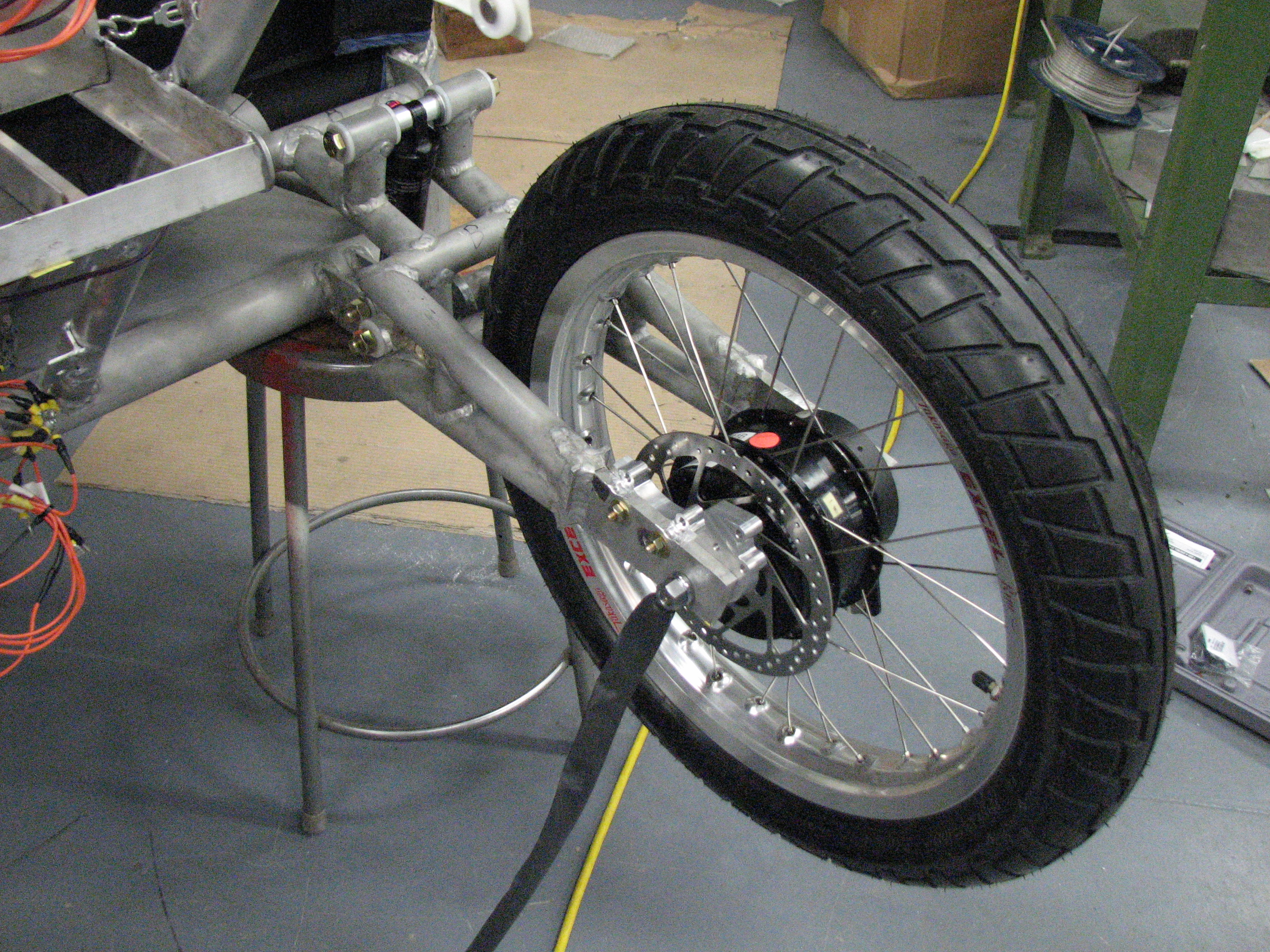
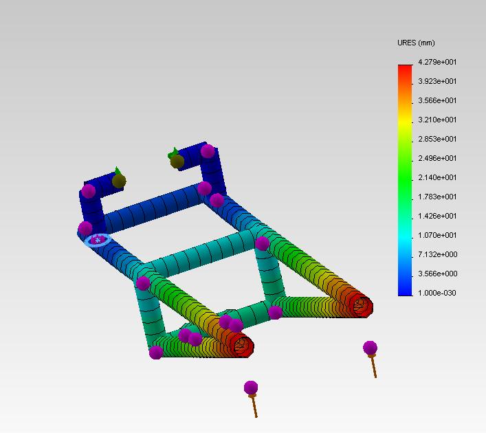
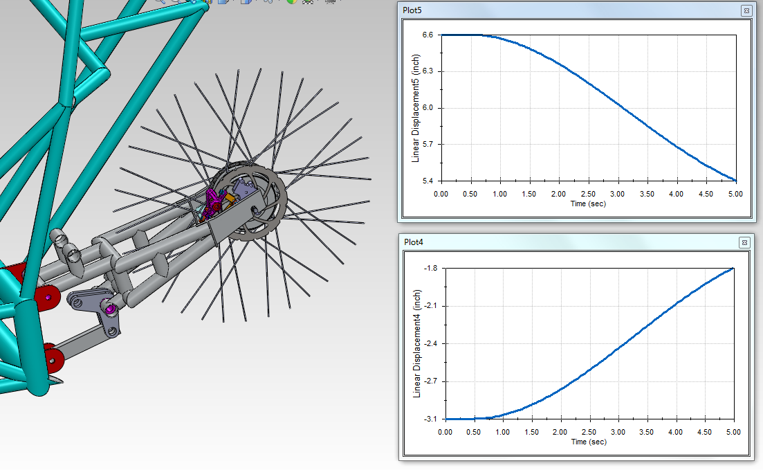
The picture above is the completed trailing arm rear suspension with attached wheel. This suspension also allows the car to stay off the ground and to absorb road impacts. Stress analysis and motion analysis was performed for this part using SolidWorks. The results are shown in the bellow two figures. The first shows a 300 N force being applied upward to the swingarm. This represents the worst case scenario when the shocks are bottomed out and the car hits a large bump. The group found that these forces were within our safety factors, and would not damage the car. The motion ratio of the movement of the wheel to the shock are shown in the second figure. This shows that the shock is operating at a good leverage ratio and will provide optimal suspension characteristics. The rear motion and leverage ratio were then physically tested. The results of this showed that the swing arm matched its theoretical aspects very closely.
