The items that were modeled using SolidWorks are listed as
follows (in order of appearance in manufacturing line): dual timing belt
conveyor with mounted plates, inspection system that also aides in cone counting
including mounting brackets, pneumatic air system to aid in the cone rejection
system, a cone rotation system to prepare the cones for stacking, individual
gate systems for controlled stacking and releasing of the cones which is linked
to the inspection system, a cleated conveyor to merge both oven manufacturing
lines, a downtime storage system for accumulation of cones during packing line
malfunctions, and also a series conveyors with which the downtime storage system
will be connected to. An overall
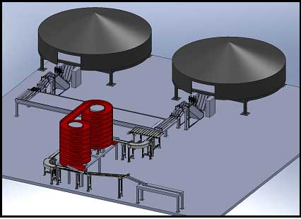
layout of the final design incorporated into the existing manufacturing lines
can be seen in Figure 1 below.

Figure 1.
SolidWorks Photo of the New Joy Cone Co.
Layout
Each individual component
is broken up and shown in Figures 2-6 below.
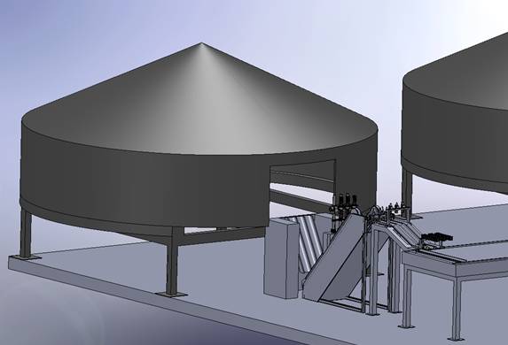
In Figure 2, the oven and trimmer are shown.
These two components will remain as they are in the current manufacturing
line. Just after the trimmer, an
inclined dual timing belt indexing conveyor was incorporated and can be seen in
both Figures 2 and 3 below. In
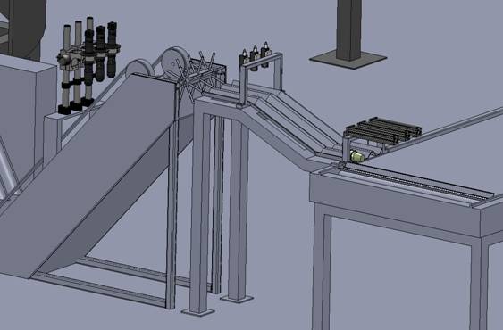
order for cones to be transferred to the rest of the manufacturing line, plates
are mounted to this conveyor which carries the individual cones to a mechanism
that will rotate the cones. This
mechanism is shown in Figure 3 as well.

Figure 2.
Oven #1 and Trimmer
As the cones travel up the
inclined conveyor, they pass through an inspection system which examines each
cone for flaws. Flawed cones
consist of those with inappropriate cracks and holes, broken cones or the
absence of a cone. Cones that do
not contain flaws will continue through the rest of the manufacturing line.
The system accomplishes this by shooting a burst of air as the conveyor
reaches a horizontal position using a pneumatic manifold with three individual
ports. This allows for the lines to
be independent of each other.
The cones are shot out of
the conveyor plates, with the top of the cone leading, onto a rotation mechanism
which can be seen in greater detail in Figure 3 below.
This rotation mechanism is also a pneumatic manifold in an octagon shape
with various hollow rods sticking out of each side of the octagon.
Once the cones reach the desired position, the pneumatic manifold also
shoots a burst of air so that the cones are shot onto a flat platform.
The cones will be shot past the flat platform which is attached to a
declined chute as well as another flat platform.
The cones are then held for counting by means of two cylindrical
actuators. Each row of actuators
operates independently based on stacking conditions.
Once the cones stack appropriately, they are transferred onto an existing
manufacturing line conveyor. Figure
3 displays all the above discussed components.

Figure 3.
Oven #1 Beginning Line
The cones from the first
oven travel down the existing manufacturing line conveyor and merge with the
cones from the second oven. The
manufacturing lines of the two ovens remain the same up to the manufacturing
line conveyor. At this point the
cones are all transferred onto a unidirectional cleated conveyor.
An additional system was added to the second oven line prior to the
cleated conveyor in order to transfer cones to this conveyor.
This conveyor acts as a traffic control mechanism managing an input of
six stacks of cones and output of one stack of cones.
The cleated conveyor transfers the stacks of cones individually onto a
series of conveyors and onto the packaging machine also known as the bagger.
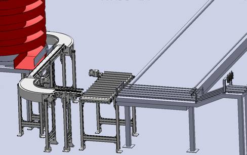
The cleated conveyor and merging area is shown in Figure 4 below.

Figure 4.
Merging Section of Both Oven Lines
The series of conveyors are
oriented and designed as follows (after the cleated conveyor): small straight
conveyor connected to a 90º turn conveyor, onto another straight conveyor,
around a 90º turn conveyor, onto another straight conveyor, around another 90º
turn conveyor, on a straight conveyor, up an inclined conveyor and on to the
packaging machine. This portion of
the system can be seen in Figure 5 below.
Figure 5.
Conveyor Lines and Storage Buffer
In the event of a packaging
line malfunction, the cones will be diverted onto a series of spiral conveyors,
shown above in Figure 5, which will store un-sleeved stacks of cones until the
malfunction has been resolved.
Diversion occurs by the use of a diverter arm connected to the first spiral
conveyor. The diverter forces cones
to merge onto the first spiral conveyor.
The cones travel up the spiral conveyor, across a bridge that is
connected to another spiral conveyor, and down the second spiral conveyor.
The cones are then reintroduced and merged onto the series of conveyors
with an additional diverter arm. A
close-up photo of a diverter arm is shown in Figure 6 below.
Figure 6.
Diverter Arm