2006-2007 Senior Capstone Project
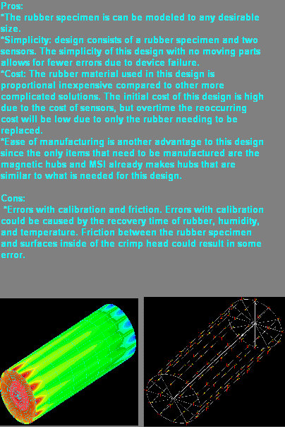
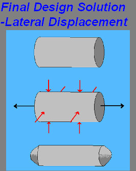
The idea behind this design is to measure the defection of a piece of rubber. A cylindrical piece of rubber will be placed inside the crimp head and the lateral movement will be measured by non contact sensors. The sensors will be mounted to the activation arms of the crimp head using magnetic hubs. Rubber has constant volume so we are able to use this information to find the force that is applied to the rubber by the crimp head. Shown are some pictures to visualize the design.
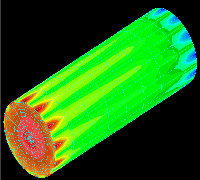
An FEA Analysis was done in COSMOS on the rubber specimen after testing to see if we could mimic the results we saw. The rubber was modeled in 12 segments such as to model what the rubber felt by the 12 segments in the crimp head. Normal forces, such as those experienced by the rubber in the crimp head were applied to the rubber specimen in COSMOS. The figure to the right is when the program was run resulting in the red and blue areas where the rubber deflects longitudinally similar to what we saw in testing. Errors were apparent with the FEA model from lack of constraints and possibly erroneous property values.
Figure 4: Rubber sample inserted into SC900 crimp head
Laser Sensor & Hub
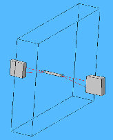

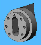
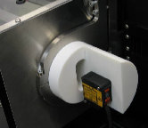
Figure 6: OMRON Senser
Figure 8
Figure 7
Figure 5
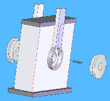
A hub was designed in Solidworks, figure 7, and manufactured in house at MSI. The hub is magnetic and attaches to the center of crimp head with the sensor attached to the hub, as seen in figures 8 and 9. Magnets were press fit radially around outer edge of the hub. This allows the sensor to be centered perfectly with the rubber specimen in the crimp head, so that it can measure the longitudinal deflection of the rubber.
We chose a Laser sensor which works by sending a beam of light that would read the deflection of a rubber specimen being crimped by the crimp head. An OMRON laser sensor was obtained for a 30 day trial period.
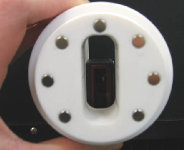
Figure 9
RESULTS
An equation to determine the pressure the rubber specimen was experiencing in the crimp head was developed based on possion's ratio. We assumed poisson's ratio to be 0.5 for a constant volume process. The equation developed can be seen below. There is a calibration factor included in this equation.
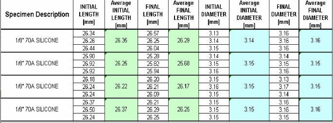
Results from testing showed that the process using rubber displacement was repeatable as can be seen from Tables 1 and 2 below. There also appeared to be a fatigue life of the rubber samples which recovers with time as seen from measurements taken in Table 2. As the rubber sample was deformed repeatedly, it appeared to lose resilience after more than 10 compressions when crimped by just 1% of its initial radius. After losing resilience, the sample was allowed a 5 minute intermission, after resilience appeared to return. No errors were apparent during testing; however, with any experiment, human error is possible.

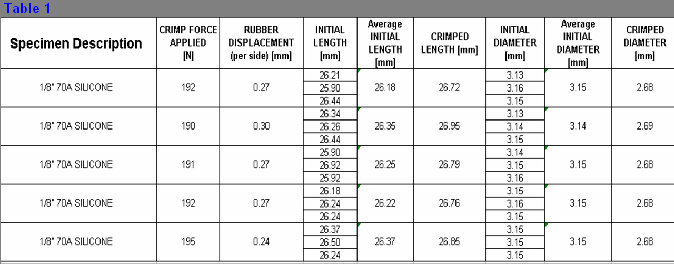
Table 2
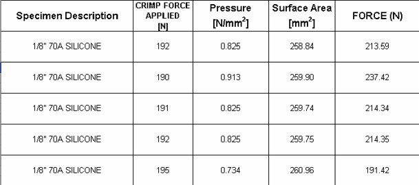
Table 2
Recommendations
It is recommended that further testing be done in order to create a calibration curve as a scaling factor for the final length within the equation given. It is also recommended that more FEA modeling be completed to predict resulting deflection more accurately. Sources of possible error for testing could have resulted from either human error or machines which are not calibrated. Sources of possible error in the FEA modeling could be caused by a lack of constraints or erroneous Young's Modulus.


