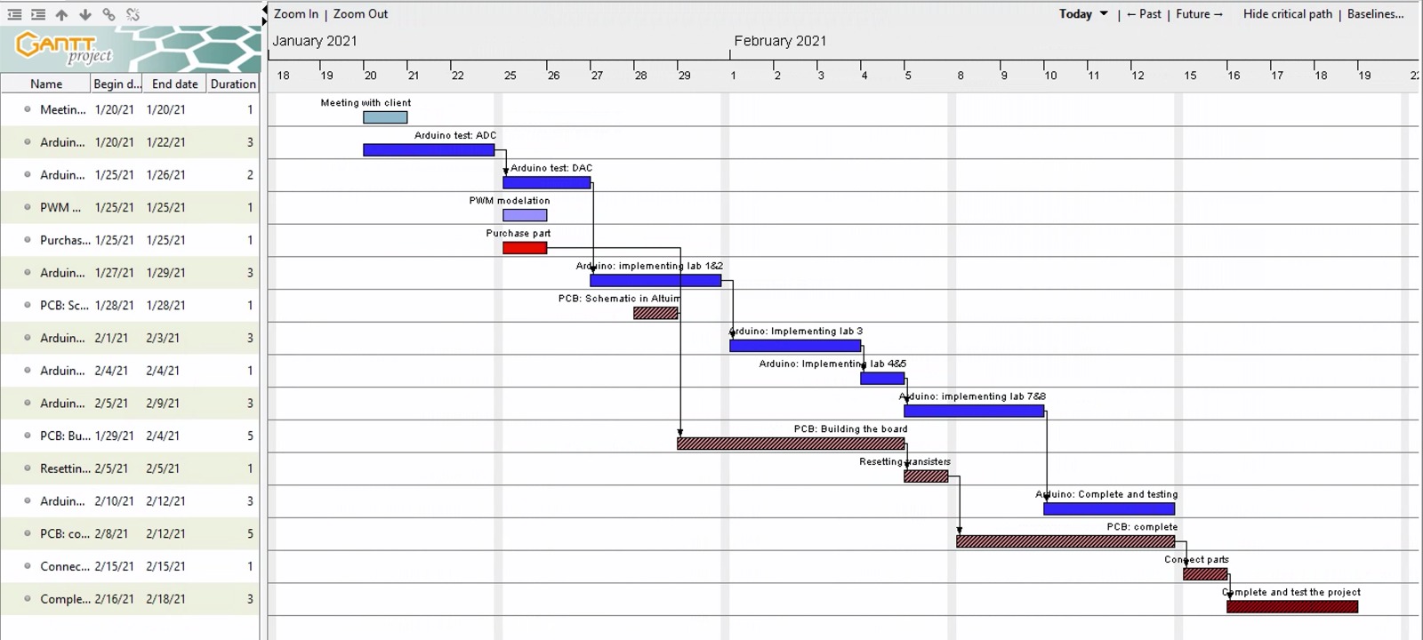
*Gantt Chart
*Overview
We have met our client several meetings, and the last meeting on Thursday, Feb25th, 2021, we agreed that there might be no time for completing the inverter board to make the size of the board smaller than the inverter board we already working on. Therefore, our requirements have changed which we will make an order for some of the components needed to build the inverter board for next year's group to finish the inverter board. So, we are focusing on the Arduino to connect it with the connectors (DB37-M2 and DB15-M2); therefore, we can connect the Arduino to the inverter board and the encoder. However, we are working on the Simulink circuit and finished part of the circuit and need some changes for the dSPACE blocks into the Arduino so the Arduino can read the circuit successfully. We are behind schedule because of some of the issues we faced with the Simulink and Arduino where we had to change the Arduino type from mega to DUE; however, we returned to the Arduino mega two weeks ago, so we had to change some of the blocks from DUE blocks to Mega blocks so it can read it. We are behind schedule because of some of the issues we face with connecting the connectors with the Arduino Mega. According to the Gantt chart, we should be testing the labs from 1 to 8. Still, because of the delays we faced while connecting the Arduino to the Simulink, we are doing lab 1 and trying to test it once we connect every part with the Arduino.
We tried our best to finish all the labs and redesign all the circuits for each lab to test them with the Arduino, but we could not complete all the labs because of the lack of time. And we tested one lab. We are behind schedule because we tried another Arduino for a couple of weeks, but after all, we returned to the Arduino MEGA 2560. After we decided which Arduino we are using, we started to connect the female connectors to the Arduino. Also, we redesign the circuit for lab one so that the Arduino can read the code from the MATLAB/Simulink. Because of the lack of time, one of the requirements is the redesigning of the inverter board. We learned how to read the schematic of the board and the pin maps for each female connector to know how to connect both connectors to the Arduino. We also learned how to use the Arduino blocks in MATLAB/Simulink.
*Testing Plan
For the testing part of our project, we have three tests that we do to verify that the project is working correctly. The first test is a unit test. For this test, we are going to test our PWM input from the Arduino on the oscilloscope and the computer screen. For the experiments two phases are depending on the PWM input for each phase the graph will show the result of each phase. The second test is the unit step test. Some of the labs require different Voltage inputs while the motor is running so it can decrease or increase depending on the instructions. In this test, we are going to implement Lab 3 which is one of the labs that require us to change the speed of the motor. This test will allow completing all the labs that require a different input while the motor is running. The final test is the integration test. For this test, we will configure the wires and pins for both DB37-M2 and the DB15-M2 to connect them to the Arduino. Connect DB37 into the inverter board and the DB15 into the encoder cable. Run the circuit into the MATLAB/Simulink to implement it into the Arduino.

